


AFL2-17AB-H61
P a g e 74
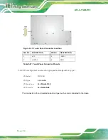
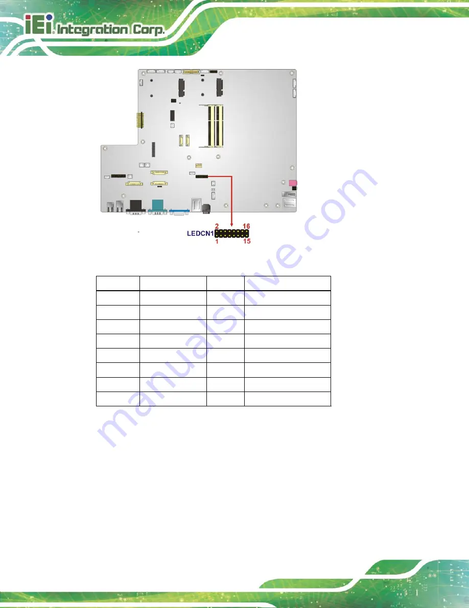
Figure 5-20: LED Connector Location
PIN NO.
DESCRIPTION
PIN NO.
DESCRIPTION
1
AUDIO_LED#
2
PWRLED01#
3
MIC_LED#
4
PWRLED02#
5
CPU_LED02#
6
AT_LED#
7
CPU_LED01#
8
ATX_LED#
9
AD_LED#
10
+V3.3S
11
WiFi_LED#
12
+V3.3S
13
BT_LED#
14
+V3.3A_EC
15
VCC_RFID
16
GROUND
Table 5-17: LED Connector Pinouts
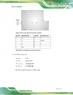
5.2.18
Lig h t Ba r Co n n e c to rs
CN La b e l:
CN1, CN2, CN3, CN4
CN Typ e :
6-pin wafer
CN Lo c a tio n :
See
CN P in o u ts :
See
Summary of Contents for AFL2-17AB-H61 Series
Page 15: ......
Page 17: ...AFL2 17AB H61 Page 1 1 Introduction Chapter 1...
Page 29: ...AFL2 17AB H61 Page 13 2 Detailed Specifications Chapter 2...
Page 35: ...AFL2 17AB H61 Page 19 3 Unpacking Chapter 3...
Page 40: ...AFL2 17AB H61 Page 24 4 Ins tallation Chapter 4...
Page 70: ...AFL2 17AB H61 Page 54 Chapter 5 5 Sys tem Motherboard...
Page 106: ...AFL2 17AB H61 Page 90 Figure 5 36 LCD panel Selection Jumper Location...
Page 107: ...AFL2 17AB H61 Page 91 6 Sys tem Maintenance Chapter 6...
Page 116: ...AFL2 17AB H61 Page 100 7 BIOS Setup Chapter 7...
Page 153: ...AFL2 17AB H61 Panel PC Page 137 8 Cooling Management Cons ole iCMC Chapter 7...
Page 162: ...AFL2 17AB H61 Panel PC Page 146 Appendix A A Regulatory Compliance...
Page 167: ...AFL2 17AB H61 Panel PC Page 151 B Safety Precautions Appendix B...
Page 173: ...AFL2 17AB H61 Panel PC Page 157 C BIOS Menu Options Appendix C...
Page 176: ...AFL2 17AB H61 Panel PC Page 160 D Hazardous Materials Dis clos ure Appendix D...