AFL2-15A-H61
Page 140
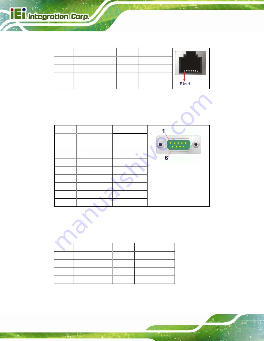
8.3.7 RS-422/485 RJ-45 Serial Port (COM3)
PIN NO.
DESCRIPTION
PIN NO.
DESCRIPTION
1
2 NC
3 RXD422-
4 NC
5 /
6 NC
7 TXD422-/TXD485-
8 NC
Table 8-35: RS-422/485 Serial Port (COM3) Pinouts
The serial device is connected to the system through the RJ-45 to COM port cable. The
DB-9 connector pinouts of the cable are listed below.
PIN NO.
RS-422
RS-485
1 RX+
-
2 RX-
-
3 TX+
DATA+
4 TX-
DATA-
5 -
-
6 -
-
7 -
-
8 -
-
9 -
-
Table 8-36: DB-9 Connector Pinout
8.3.8 USB 2.0 Connectors (USB01)
PIN NO.
DESCRIPTION
PIN NO.
DESCRIPTION
1 POWER
2 -DATA0
3 +DATA0
4 GND
5 POWER
6 -DATA1
7 +DATA1
8 GND
Table 8-37: USB 2.0 Connectors (USB01) Pinouts
Summary of Contents for AFL2-15A-H61 series
Page 14: ...AFL2 15A H61 Page XIV Figure C 42 Disable Automatically Restart 188...
Page 18: ...AFL2 15A H61 Page 1 1 Introduction Chapter 1...
Page 31: ...AFL2 15A H61 Page 14 2 Unpacking Chapter 2...
Page 36: ...AFL2 15A H61 Page 19 3 Installation Chapter 3...
Page 61: ...AFL2 15A H61 Page 44 4 BIOS Setup Chapter 4...
Page 97: ...AFL2 15A H61 Page 80 5 Software Drivers Chapter 5...
Page 123: ...AFL2 15A H61 Page 106 Figure 5 41 USB 3 0 Driver Update Complete...
Page 124: ...AFL2 15A H61 Page 107 6 System Monitoring iCMC Chapter 6...
Page 133: ...AFL2 15A H61 Page 116 7 System Maintenance Chapter 7...
Page 142: ...AFL2 15A H61 Page 125 8 Interface Connectors Chapter 8...
Page 160: ...AFL2 15A H61 Page 143 A Safety Precautions Appendix A...
Page 165: ...AFL2 15A H61 Page 148 B BIOS Menu Options Appendix B...
Page 168: ...AFL2 15A H61 Page 151 Appendix C C One Key Recovery...
Page 176: ...AFL2 15A H61 Page 159 Figure C 5 Partition Creation Commands...
Page 210: ...AFL2 15A H61 Page 193 D Hazardous Materials Disclosure Appendix D...


