AFL-xxA-N270 Series Panel PC
Page 54
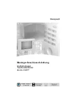
Figure 4-25: LAN Connection
Step 3:
Insert the LAN cable RJ-45 connector.
Once aligned, gently insert the LAN
cable RJ-45 connector into the onboard RJ-45 connector.
Step 0:
4.11.2 Serial Device Connection
The AFOLUX AFL-xxA-N270 Series has two male DB-9 connectors on the bottom panel
for serial devices to be connected. Follow the steps below to connect a serial device to the
AFOLUX AFL-xxA-N270 Series panel PC.
Step 1:
Locate the DB-9 connector
. The location of the DB-9 connector is shown in
Chapter 2
.
Step 2:
Insert the serial connector
. Insert the DB-9 connector of a serial device into
the DB-9 connector on the bottom panel. See
Summary of Contents for AFL A-N270 Series
Page 15: ...AFL xxA N270 Series Panel PC Page 1 1 Introduction Chapter 1...
Page 23: ...AFL xxA N270 Series Panel PC Page 9 2 Detailed Specifications Chapter 2...
Page 36: ...AFL xxA N270 Series Panel PC Page 22 Figure 2 13 PIFA Antenna and Wireless Module...
Page 37: ...AFL xxA N270 Series Panel PC Page 23 3 Unpacking Chapter 3...
Page 42: ...AFL xxA N270 Series Panel PC Page 28 4 Installation Chapter 4...
Page 71: ...AFL xxA N270 Series Panel PC Page 57 5 System Maintenance Chapter 5...
Page 78: ...AFL xxA N270 Series Panel PC Page 64 6 AMI BIOS Setup Chapter 6...
Page 118: ...AFL xxA N270 Series Panel PC Page 104 7 Software Drivers Chapter 7...
Page 146: ...AFL xxA N270 Series Panel PC Page 132 Step 1 A System Specifications Appendix A...
Page 151: ...AFL xxA N270 Series Panel PC Page 137 B Safety Precautions Appendix B...
Page 157: ...AFL xxA N270 Series Panel PC Page 143 C BIOS Configuration Options Appendix C...
Page 161: ...AFL xxA N270 Series Panel PC Page 147 D Watchdog Timer Appendix D...
Page 164: ...AFL xxA N270 Series Panel PC Page 150 E Hazardous Materials Disclosure Appendix E...
Page 168: ...AFL xxA N270 Series Panel PC Page 154 F Index...