background image


 28 


 Check the door lock operation and the connection between the door lock and the 100W. 

1. Check the wiring between the door lock and the 100W to see if there is any short circuit or cutoff. 
2. Check the operation of the door lock. Remove the door lock from the 100W and check the relay output from 

the 100W with a measuring instrument. If the relay output from the 100W is normal, replace the door lock.   

Summary of Contents for iPass IP100W

Page 1: ...User s Manual ...

Page 2: ...ption 5 6 Identifying Supplied Parts 5 7 Installation 5 8 Wiring Color Table 6 9 System Wiring for Typical Application 7 10 Initial Setup 9 11 Operation 11 12 Setting Changes 12 13 Initialization 21 14 FCC Registration Information 22 15 Troubleshooting 23 16 Warranty Policy and Limitatin of Liability 29 17 Template 31 ...

Page 3: ...anual Improper adjustment of other controls that are not covered by this manual may damage the unit and will often require extensive work by a qualified technician to restore normal operation d If the product exhibits a distinct change in performance 2 General The Star 100W iPASS IP100W is an intelligent PIN Proximity Single Door Controller that combines the convenience of wireless entry with the ...

Page 4: ...its RF or PIN Options 4ch Voice Auto dialer Compatible Software STAR 100R PRO Weather proofed Comparison Table 100W 125KHz PSK modulation IP100W 125KHz ASK EM Format 4 Specification Model 100W IP100W CPU Dual 8bit Microprocessor Program Memory 20KByte ROM Memory Data Memory 2KByte EEPROM User 512 Users Passive Type IDK50 IMC125 Up to 2 inches 5 cm IDC80 IDC170 Up to 4 inches 10 cm IPK50 Up to 2 in...

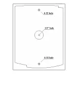
Page 5: ...s Certification UL FCC CE MIC 5 Front Panel Description Main Unit of Star 100W iPASS 100W 6 Identifying Supplied Parts Please unpack and check the contents of the package Main Unit Wall Mount O Ring User s Manual 1ea 1ea 5ea 1copy 3 5 40 Screw 3 5 12 Screw Anchor Bolt 4ea 4ea 4ea 7 Installation 7 1 Tear off Page 31 and use the provided template to drill two 6 32 holes and one 1 2 hole on the prope...

Page 6: ...nd render its effectiveness 7 3 Insert 5 O rings to the wall mount as indicated then route the cable of the main unit through the center hole and push the main unit to wall mount to lock the main unit and make sure that the main unit is locked with the wall mount 8 Wiring Color Table SIGNAL COLOR Main Power 12V Red Power Ground GND Black Door Relay Out COM Gray with Red stripe Door Relay Out NC Bl...

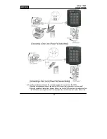
Page 7: ...n Pink Wiegand Data 1 In Cyan Exit Button In Yellow with Red stripe Door Contact In Green Aux In 1 Orange Aux In 2 Green with White stripe Aux In 3 Brown RS232 TX Gray RS232 RX Blue RS232 GND Yellow Please cut out the tail connector before installation 9 System Wiring for Typical Application ...

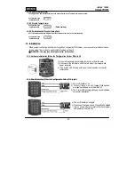
Page 8: ...ton to Exit Button Input Yellow Red banded wire Connect the other wire of Exit Button to Power GND wire If a normally closed Exit button is used see section 12 67 to change the detection scheme from the default 9 5 Door Contact Sensor Connection Connect Door Contact sensor COM wire to Door Contact Input Green wire Connect Door Contact sensor NO wire to Power GND wire If a normally closed Door Cont...

Page 9: ... a minimum set of default values but it does not have any other preprogrammed values or user s data in it therefore Initial Setup is required upon the first time the unit is powered up in order to operate the unit properly 10 1 Registration of RF Cards for RF CARD ONLY MODE 1 Apply 12VDC to the unit All 3 LEDs will be flashing with a powered up melody do mi sol me do do mi sol do 2 Press on the ke...

Page 10: ...er to register Configuration PIN then to register User Access PIN s one by one and then enter Configuration PIN to complete the registration Configuration PIN User Access PIN 4 The first 4 6 digit PIN becomes the Configuration PIN and the subsequent 4 6 digit PINs are registered as User Access PINs Once all User Access PINs have been registered enter the Configuration PIN again to complete the reg...

Page 11: ...K ACCESS MODE Disable 5 Chime Bell output Enable Chime Bell activation time 05 sec 6 Melody sound Enable 7 Keypad lock out time when Try Out error detected 01 min 8 Detect all inputs from H to L 9 Activate TTL output to L 10 Delay time to activate SECURE MODE 00 min 11 Door Open time out for Door Contact sensor 00 sec 12 Number of times of Try out 05 times 13 Input keypress time out time 20 sec 14...

Page 12: ...nge to Secure Mode The Secure Mode will revert back to the normal mode when a registered card or PIN is presented entered 11 6 DURESS Alarm In case of Duress enter the 2 digit Duress Password and the door will open as usual however the Duress Alarm TTL Output will activate an external Auto Dialer to notify the appropriate personnel See section 9 7 and 12 29 for more instructions on this feature 11...

Page 13: ...ime set by command 25 36 Test Alarm time set by command 26 37 Test Alarm time set by command 27 39 Change Chime Bell activating time 41 Open door unconditionally 42 Close door unconditionally 43 Enable QUICK ACCESS MODE 44 Disable QUICK ACCESS MODE 45 Enable Toggle Mode for Lock control 46 Disable Toggle Mode for Lock control 47 Enable Unlock followed by Door Contact 48 Disable Unlock followed by ...

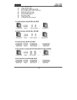
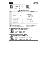
Page 14: ...Access Cards RF CARD ONLY MODE Configuration Card Command Cards to be registered Configuration Card 12 12 Add User Access Cards RF CARD PIN MODE Configuration Card Command Cards to be registered Configuration Card 12 13 Add User Access PIN PIN ONLY MODE Configuration PIN Command PINs to be registered Configuration PIN 12 14 1 Delete User Access Cards RF CARD ONLY MODE RF CARD PIN MODE Configuratio...

Page 15: ...re Mode 50 Door Relay 01 OM 51 EX2 Activate Alarm Relay TTL only in Secure mode Secure Mode 00 Alarm Relay TTL 06 OM 06 tt tt is the activating time value seconds from 01sec to 99sec tt value 00sec means no operation PW PW is the 2 digit Password for Duress Alarm Do not use 77 for PW as it is used for Secure Mode mm mm is the activating time value minutes from 01min to 99min mm value 00min means n...

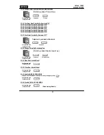
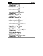
Page 16: ... TTL time Configuration PIN 12 25 Change Alarm Time When AUX Input 1 Detected 12 26 Change Alarm Time When AUX Input 2 Detected 12 27 Change Alarm Time When AUX Input 3 Detected Refer to Table 1 for OM tt 00 99 sec Configuration Card Command Output Mode Door time Alarm Time TTL time Configuration PIN 12 28 Change Alarm Time When Magnet Detected Refer to Table 1 for OM tt 00 99 sec Configuration Ca...

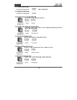
Page 17: ...Set By Command 27 Outputs set by command will be tested Configuration Card Command Configuration PIN 12 39 Change Chime Bell Activating Time tt 00 99 sec Default Chime Bell time 05 sec Configuration Card Command Chime Bell time Configuration PIN 12 41 Open Door Unconditional Configuration Card Configuration PIN 12 42 Close Door Unconditional Configuration Card Configuration PIN 12 43 Enable QUICK ...

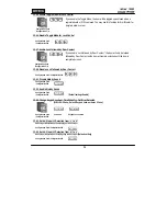
Page 18: ...oor Contact Configuration Card Configuration PIN 12 51 Disable Melody Sound Configuration Card Configuration PIN 12 52 Enable Melody Sound Configuration Card Configuration PIN Default setting Enable 12 60 Change Keypad Lock out Time When Try Out Error Detected mm 00 99 min Default Keypad Lock out time 01 min Configuration Card Command Keypad Lock out time Configuration PIN 12 61 Set AUX Input 1 De...

Page 19: ...alling edge of Exit Button input Default setting Configuration Card Configuration PIN 12 69 Set Door Contact Sensor Input Detection from L to H Door Contact input is detected on the rising edge of Door Contact input Configuration Card Configuration PIN 12 70 Set Door Contact Sensor Input Detection from H to L Door Contact input is detected on the falling edge of Door Contact input Default setting ...

Page 20: ...etect Door Contact Sensor refer to 12 24 for Alarm time settings Configuration Card Command Door Open time out Configuration PIN 12 82 Set Number of Times of Try Out NN 00 99 times Default Try out numbers 05 times Configuration Card Command Try out numbers Configuration PIN 12 83 Set Input Keypress Time out Time tt 10 99 sec Default Keypress time out 20 sec Minimum tt 10 sec Configuration Card Com...

Page 21: ...ze function on the unit WARNING You may lose all setup data after Initialization 13 1 Hardware Initialization When the Configuration Card or PIN is lost 13 2 Wire Initialization When the Configuration Card or PIN is lost 1 Open the top case by screwing the four bolts out from the back 2 As shown in the left picture short the two pins of the jumper while power is applied 3 The 3 color LED blinking ...

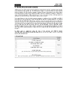
Page 22: ...uant to Part 15 of the FCC Rules These limits are designed to this equipment generates uses and can radiate radio frequency energy and if not installed and used in accordance with the instructions may cause harmful interference to radio communications However there is no guarantee that interference will not occur in a particular installation If this equipment does cause harmful interference to rad...

Page 23: ... is in the normal operation mode It is caused by system malfunctions Try turning the power of 100W off and on If the problem still persists initialize the product See 13 Initialization for more information about how to initialize your 100W Problem The 100W returns to the Normal Operation Mode while you are registering User Access Cards or changing settings in the Configuration Mode Cause Time out ...

Page 24: ...lete the User Access Card s e Press PIN ENT Repeat this process if there re more than one card to delete f Present the Configuration Card or press the Configuration PIN ENT Lost the Configuration Card 1 If the Configuration Card is missing you cannot perform registration deletion setting adjustment 2 Initialize the product See 13 Initialization for more information about how to initialize your 100...

Page 25: ... the Configuration PIN ENT 2 Enter 73 ENT to enable Keypad Input To Enter ID Number See 12 Setting Changes for more details If the buzzer does not beep 1 If the buzzer beeps after a certain length of time passes see the following a If unregistered IDs are entered 5 times default in a row keys on the keypad do not function for 1 min default b The following is about how to configure the maximum numb...

Page 26: ... connected to the Exit Button If the 100W responds when the exit button is pressed replace the exit button because it is faulty If the 100W does not respond the 100W is malfunctioning Initialize the product Problem An RF card is successfully recognized by the exit reader but the data transmission to the PC fails or incorrect data is transmitted Cause Incorrect connection between the exit reader an...

Page 27: ...With a measuring instrument check if any noise is present in the communication cable If a trace of noise is detected enhance the GND signal by using the shield wire and a spare wire of the cable as GND It is recommendable to stabilize communication signals by using a repeater See 7 Installation to find out more about wiring Problem A door lock won t work Cause An error in connection between the do...

Page 28: ...e wiring between the door lock and the 100W to see if there is any short circuit or cutoff 2 Check the operation of the door lock Remove the door lock from the 100W and check the relay output from the 100W with a measuring instrument If the relay output from the 100W is normal replace the door lock ...

Page 29: ...t property is located where this product will be used it would be extremely difficult to determine the actual damages that may result from a failure of the product to perform as anticipated and the low price of this product is based upon the nature of the product provided and the limited liability that IDTECK assumes IDTECK IS NOT RESPONSIBLE FOR ANY PERSONAL INJURY PROPERTY DAMAGE OR LOSS DIRECT ...

Page 30: ...ation Code 1 Company Name 2 Model Name 3 Serial No 4 Original Invoice No 5 Distributor 6 Purchasing Date 7 RMA Request Date Please check your problems Card Reading Power Keypad Communication Relay LCD LED Buzzer Registration Others IDTECK RMA Center 3F 10 10 1 10 2 Dodang Dong Weonmi Gu Bucheon Si Gyeonggi Do 157 030 Korea Telephone 82 2 2659 0055 HQ 82 32 671 5642 RMA Center Fax 82 2 2659 0086 HQ...

Page 31: ...31 17 Template MEMO ...

Page 32: ...100WHE1X The specifications contained in this manual are subject to change without notice at any time 5F Ace Techno Tower B D 684 1 Deungchon Dong Gangseo Gu Seoul 157 030 Korea Tel 82 2 2659 0055 Fax 82 2 2659 0086 E mail webmaster idteck com ...

Reviews: