


Communication
9
p.21
1
Board ID Setting for RS485 / RS422 Communication
Board ID is the unique address of the device to communicate with PC and it is set by 8 DIP s
witches. Each DIP switch has assigned address values. Board ID is decided depending on pos
itions of switch set to ‘ON’ or ‘OFF’ position.
From ‘000’ to ‘254’, total 255ea of Board ID can be set and Board ID 255 is used for system i
nitialization, thus; you cannot use it as Board ID.
The method of setting Board ID differs depending on the version of product. Therefore, you
should check the version and then set Board ID.
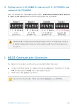
1.1
For 8.0.0 and higher version of FGR006 / 8.1.0 and higher version of IP-FGR
006 / 4.0.0 and higher version of FGR006SR
Each of 8 DIP switches has assigned address values as figure below.
Board ID is sum values o
f each switch that are set to ‘ON’ position.
Refer to the examples below and set Board ID.
Summary of Contents for FINGER006SR
Page 1: ......
Page 14: ...Identifying Supplied Parts 5 p 9 Please unpack and check the contents of the box ...
Page 25: ...p 20 Wiring 4 4 External Reader Connection ...
Page 29: ...p 24 RS422 Communication Connection Computer Install and run the application software ...
Page 35: ...p 30 External RS232C Stereo Jack Option ...
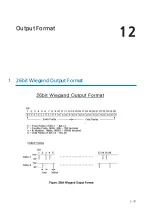
Page 38: ...Output Format 12 p 33 1 26bit Wiegand Output Format ...
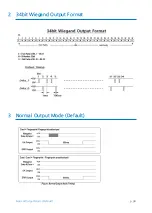
Page 39: ...p 34 Normal Output Mode Default 2 34bit Wiegand Output Format 3 Normal Output Mode Default ...
Page 40: ...Output Format p 35 4 Extension Output Mode Selectable using the softwar e ...


