


Installation of the Product
p.19
4
Wiring
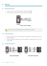
4.1
Power Connections
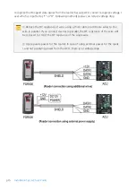
1.
C12V(+) wire of Power Supply to Red wire of FGR006
2.
Connect GND(-) wire of Power Supply to Black wire of FGR006
* Even in case of using external power, you MUST connect GND(-).
4.2
Input Connection
●
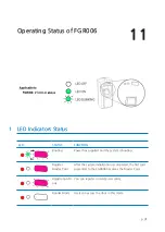
The Green LED is turned on if the LED Control Input(Blue with White stripe) wire is conn
ected to the GND.
●
A beep is generated if the Beeper Control Input(White with Red stripe) wire is connecte
d to the GND.
4.3
Output Connections
Summary of Contents for FINGER006SR
Page 1: ......
Page 14: ...Identifying Supplied Parts 5 p 9 Please unpack and check the contents of the box ...
Page 25: ...p 20 Wiring 4 4 External Reader Connection ...
Page 29: ...p 24 RS422 Communication Connection Computer Install and run the application software ...
Page 35: ...p 30 External RS232C Stereo Jack Option ...
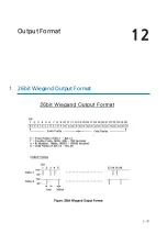
Page 38: ...Output Format 12 p 33 1 26bit Wiegand Output Format ...
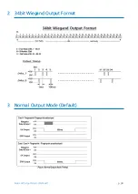
Page 39: ...p 34 Normal Output Mode Default 2 34bit Wiegand Output Format 3 Normal Output Mode Default ...
Page 40: ...Output Format p 35 4 Extension Output Mode Selectable using the softwar e ...


