ZMOD4410 Evaluation Kit User Manual
© 2019 Integrated Device Technology, Inc.
7
April 3, 2019
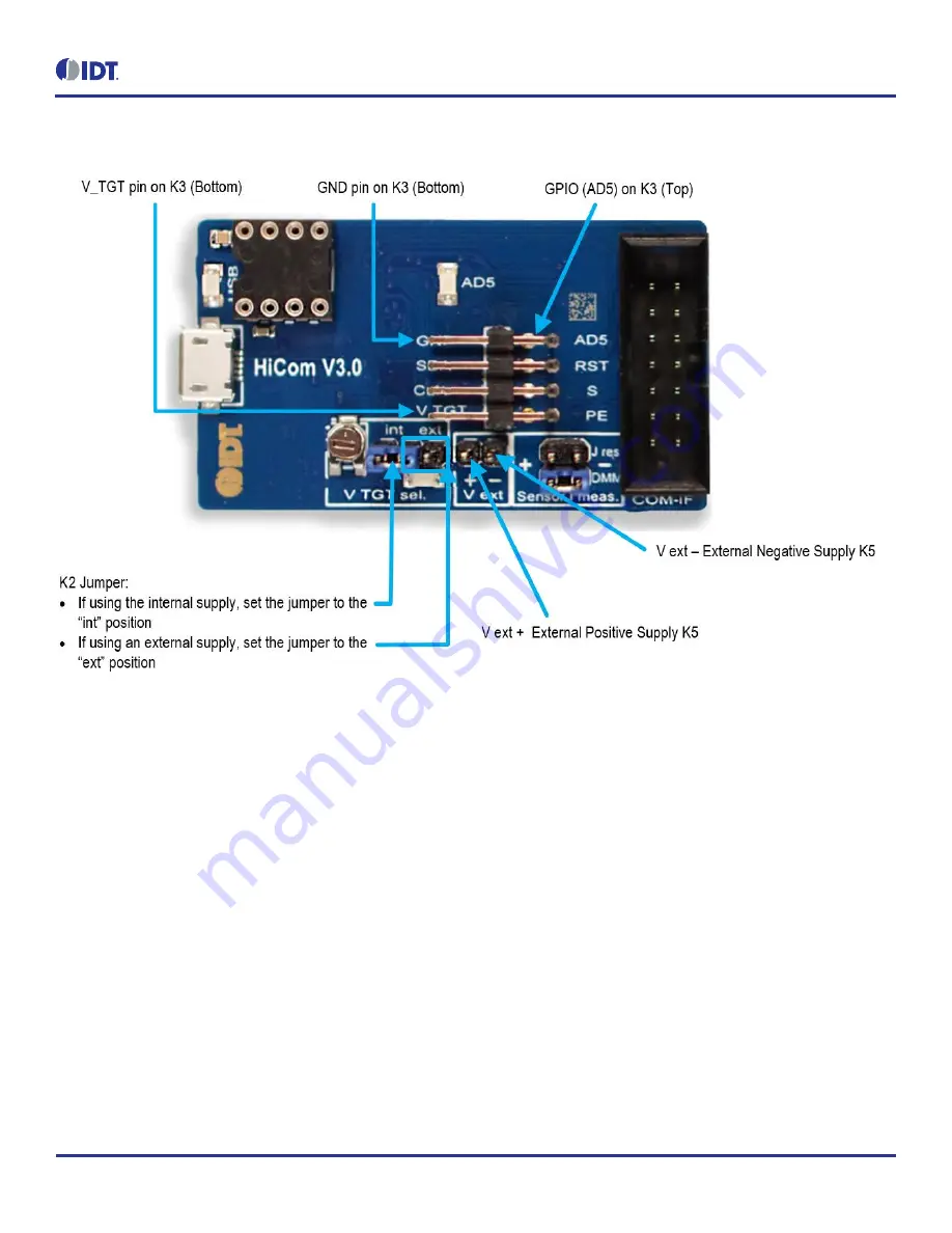
Figure 3. Jumper Settings, Connections, and Test Points on the Communication Board for the
Internal or External Supply Voltage
Page 1: ...cation Board has devices mounted on both sides The components on the top side generate a stable supply voltage A potentiometer can be used to adjust the internal supply voltage in the typical range fr...
Page 2: ...ARISE BY REASON OF USAGE OF TRADE CUSTOM OR COURSE OF DEALING Restrictions in Use IDT s ZMOD4410 Evaluation Kit consisting of the ZMOD4410 HiCom Communication Board ZMOD4410 Sensor Board and the ZMOD...
Page 3: ...nd Low Power Operation Mode 8 Figure 5 Analysis Tab for Measurement Mode Standard Operation and Low Power Operation 10 Figure 6 Analysis Tab for Measurement Mode Odor 11 Figure 7 Communication Board S...
Page 4: ...nts 1GB RAM Hard drive with at least 500MB free space 1 USB port Windows Vista Windows 7 Windows 8 Windows 10 Internet access for initial download of the drivers and software Important Before installi...
Page 5: ...care to ensure the proper orientation of the Sensor Board as shown on page 1 3 Insert the micro USB cable into the X1 connector on the Communication Board and connect it to a free USB port on the use...
Page 6: ...MOD4410 Sensor Board AD5 is a GPIO pin that can be controlled via the software in the Odor measurement mode K4 14 pin connector This is the connector for installing the ZMOD4410 Sensor Board on the Co...
Page 7: ...10 Evaluation Kit User Manual 2019 Integrated Device Technology Inc 7 April 3 2019 Figure 3 Jumper Settings Connections and Test Points on the Communication Board for the Internal or External Supply V...
Page 8: ...asurements When the start sensor button is clicked the measurement starts running continuously with the given sample time 2 seconds fixed for Standard Operation 5 seconds default for Odor Operation an...
Page 9: ...path and file name A comment for example Apply test gas can be added to the data entry by adding a string to the Add comment to next measurement field and then clicking the ok button If a measurement...
Page 10: ...Power Operation For Odor Operation Click on the tab to display the Analysis tab see Figure 6 The Analysis tab shows two plots Algorithmic output signal with indication on trigger activation times AD5...
Page 11: ...format One sensor will be processed and displayed at a time For Standard Operation and Low Power Operation the default algorithms applied in the Analysis tab calculate gas concentrations for eCO2 and...
Page 12: ...ialization measurements Algorithm Result for Standard Operation and Low Power Operation After the stabilization measurements the Algorithm Result field shows a colored bar representing the results fro...
Page 13: ...ZMOD4410 Evaluation Kit User Manual 2019 Integrated Device Technology Inc 13 April 3 2019 3 Schematics Figure 7 Communication Board Schematic Page 1...
Page 14: ...ZMOD4410 Evaluation Kit User Manual 2019 Integrated Device Technology Inc 14 April 3 2019 Figure 8 Communication Board Schematic Page 2...
Page 15: ...ZMOD4410 Evaluation Kit User Manual 2019 Integrated Device Technology Inc 15 April 3 2019 Figure 9 Sensor Board Schematic...
Page 16: ...nF 0603 10 C13 100nF 0603 11 C14 100nF 0603 12 C15 100nF 0603 13 C16 100nF 0603 14 C17 10 F 16V 0805 15 C18 27pF 0603 16 C19 27pF 0603 17 C20 10 F 16V 0805 18 C21 10 F 16V 0805 19 C22 100nF 0603 20 C2...
Page 17: ...0 42 K4 K2X7 LH 14 43 K5 V_EXT 1X02 44 L1 10 H 1210 45 L2 10 H 1210 46 L3 10 H 1210 47 Modul1 Honeywell480 3652 1 ND DIL8 SMD SOCKEL 48 Q1 12 00MHz QUARZ ABM3 49 R1 1k 0805 50 R2 1k 0805 51 R3 1 6k 08...
Page 18: ...able 4 Sensor Board BOM Designator Quantity Manufacturer Manufacturer Part Number C1 1 Taiyo Yuden LMK105BJ104KV F U1 1 IDT ZMOD4410 X1 1 Sullins SFH11 PBPC D07 ST BK 5 Board Layout Figure 10 HiCom Co...
Page 19: ...ZMOD4410 Evaluation Kit User Manual 2019 Integrated Device Technology Inc 19 April 3 2019 Figure 12 Sensor Board Layout Top Layer Figure 13 Sensor Board Layout Bottom Layer...
Page 20: ...and are not guaranteed to perform the same way when installed in customer products The information contained herein is provided without representation or warranty of any kind whether express or impli...