


IDT Transparent Mode Operation
Generic PCI to PCI Bridge Register Definition
PES12N3 User Manual
9 - 50
June 7, 2006
Notes
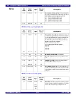
ECFGDATA - Extended Configuration Space Access Data (0x0FC)
PCI Express Virtual Channel Capability
PCIEVCECAP - PCI Express Virtual Channel Enhanced Capability Header (0x100)
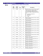
PVCCAP1- Port VC Capability 1 (0x104)
31:12
Reserved
RO
0x0
Reserved.
Bit
Field
Field
Name
Type
Default
Value
Description
31:0
DATA
RW
0x0
Configuration Data. A read from this field will return the
configuration space register value pointed to by the ECF-
GADDR register. A write to this field will update the con-
tents of the configuration space register pointed to by the
ECFGADDR register with the value written. For both reads
and writes, the byte enables correspond to those used to
access this field.
When the ECFGADDR register points to the ECFGDATA
register, then reads from ECFGDATA return zero and
writes are ignored. When the ECFGADDR register points
to itself, writes to the ECFGDATA register modify the con-
tents of the ECFGADDR register.
SMBus reads of this field return a value of zero and SMBus
writes have no effect.
Bit
Field
Field
Name
Type
Default
Value
Description
15:0
CAPID
RO
0x2
Capability ID. The value of 0x2. indicates a virtual channel
capability structure.
19:16
CAPVER
RO
0x1
Capability Version. The value of 0x1. indicates compati-
bility with version 1 of the specification.
31:20
NXTPTR
RO
0x0
Next Pointer. The value of 0x0 indicates that there are no
extended capabilities.
Bit
Field
Field
Name
Type
Default
Value
Description
2:0
EVCCNT
RO
0x0
Extended VC Count. The value 0x0 indicates only imple-
mentation of the default VC.
6:4
LPEVCCNT
RO
0x0
Low Priority Extended VC Count. The value of 0x0 indi-
cates only implementation of the default VC.
9:8
REFCLK
RO
0x0
Reference Clock. Time-based WRR is not implemented.
Bit
Field
Field
Name
Type
Default
Value
Description
Summary of Contents for 89HPES12N3
Page 10: ...IDT Table of Contents PES12N3 User Manual iv June 7 2006 Notes...
Page 14: ...IDT List of Figures PES12N3 User Manual viii June 7 2006 Notes...
Page 36: ...IDT Clocking Reset and Initialization Reset PES12N3 User Manual 2 8 June 7 2006 Notes...
Page 40: ...IDT Link Operation Slot Power Limit Support PES12N3 User Manual 3 4 June 7 2006 Notes...
Page 50: ...IDT Switch Operation Switch Core Errors PES12N3 User Manual 4 10 June 7 2006 Notes...
Page 54: ...IDT Power Management Active State Power Management PES12N3 User Manual 5 4 June 7 2006 Notes...
Page 62: ...IDT Hot Plug and Hot Swap Hot Swap PES12N3 User Manual 6 8 June 7 2006 Notes...
Page 78: ...IDT SMBus Interfaces Slave SMBus Interface PES12N3 User Manual 7 16 June 7 2006 Notes...
Page 148: ...IDT Test and Debug SerDes Test Clock PES12N3 User Manual 10 6 June 7 2006...
Page 158: ...IDT JTAG Boundary Scan Usage Considerations PES12N3 User Manual 11 10 June 7 2006 Notes...