


Part 1 – Introduction
10
Rear Panel Connections
Power Cable Connection
This DVR does not feature a separate power on/off
button and will turn on the moment power is supplied.
Connect the connector(12V) of adapter to the DVR and
then connect the AC power cable of adapter to the
power outlet.
•
Organize the power cable so that it will not cause
people to trip over or become damaged from chairs,
cabinets, desks, and other objects in the vicinity. Do
not run the power cable underneath a rug or carpet.
•
Do not connect multiple devices to a single power
outlet.
USB Port
●
Storage Device Connection
Connect an external USB hard drive or a USB flash
memory device to one of the USB ports for use with
the Clip Copy feature. The external storage device
should be placed as close to the DVR as possible. It is
recommended that you use a connection cable that is
no longer than 180cm in length. Use the connection
cable included with your external storage device to
connect the device to one of DVR's USB ports. For
more information Clip Copy, refer to the
Clip Copy in
the operation manual
.
●
Peripheral Device Connection
Use the USB ports to connect peripherals such as a
USB mouse to the DVR. You can also use a USB-to-
serial converter and connect multiple text-in devices
to the DVR at the same time.
For USB flash memory devices, the DVR supports
the FAT32 file format only.
Network Connection
This DVR is capable of connecting to networks via an
ethernet connector. Connect an RJ-45 cable (Cat5,
Cat5e, or Cat6) to the DVR's network port. It's possible to
operate and upgrade the DVR remotely over a network.
Fore more information on ethernet connection setup,
refer to
Network Setup in the operation manual
.
Green LED on the right will begin to turn on if
connected a 100Mbps network. The LED will turn off if
connected a 10Mbps network. Orange LED on the left
will flash once when a link has been established.
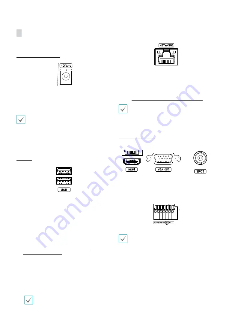
Monitor Connection
Connect to the
HDMI
,
VGA
,
SPOT OUT
port.
Alarm Connection
Connect alarm connectors to these ports.
Press down on the button and insert the cable into
the opening. Release the button and then pull on the
cable slightly to ensure it is held securely in place. To
disconnect the cable, press down on the button again
and pull the cable out.