194
A.
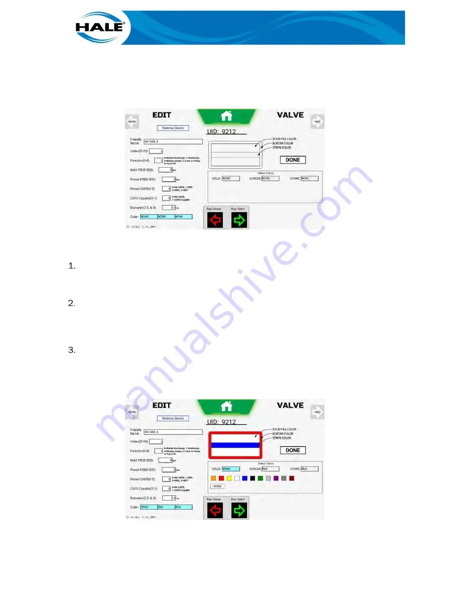
After selecting desired valve, touch text box of desired area of icon to assign/
change a color. Color swatches and NONE buttons are displayed.
NOTE
Left-most box = solid fill color; Center box = border color; Right-most box = stripe color.
Figure 162. Valve Edit – Color Assignments
B.
Assign colors as follows.
If solid portion of icon is desired, touch SOLID box and assign/change color as follows.
a)
If a color is desired, touch desired swatch.
b)
If a change to no color is desired, touch NONE button.
If border portion of icon is desired, touch BORDER box and assign/change color as fol-
lows.
a)
If a color is desired, touch desired swatch.
b)
If a change to no color is desired, touch NONE button.
If border portion of icon is desired, touch BORDER box and assign/change color as fol-
lows.
c)
If a color is desired, touch desired swatch.
d)
If a change to no color is desired, touch NONE button.
Figure 163. Color Assignment Swatches
Summary of Contents for Hale Sam
Page 2: ......
Page 37: ...17 Figure 14 SAM Blue CAN Buss Architecture With Three SAM Control Centers Diagram...
Page 38: ...18 Figure 15 SAM Green CAN Buss Architecture With Three SAM Control Centers Diagram...
Page 39: ...19 Figure 16 SAM Red CAN Buss Architecture With Three SAM Control Centers Diagram...
Page 40: ...20 Figure 17 SAM System Drain And Pneumatic Diagram...
Page 41: ...21 Figure 18 SAM Speaks Diagram...
Page 42: ......
Page 58: ...38 THIS PAGE INTENTIONALLY BLANK...
Page 62: ...42 THIS PAGE INTENTIONALLY BLANK...
Page 192: ...172 THIS PAGE INTENTIONALLY BLANK...
Page 206: ...186 THIS PAGE INTENTIONALLY BLANK...
Page 220: ...200 THIS PAGE INTENTIONALLY BLANK...


