19: P
ULSE
O
UTPUT
I
NSTRUCTIONS
19-28
FT1A S
MART
A
XIS
U
SER
’
S
M
ANUAL
FT9Y-B1382
4. S3 (source 3): Proximity signal
S3 specifies the proximity signal. Specify either an external input or an internal relay.
The external input can be specified as (I0 to I35) or the internal relay can be specified as (M0 to M1277).
Notes:
Do not use the same input or internal relay as the proximity signal for the ZRN1 and ZRN2 instructions. If they operate simultaneously, pulse
output may not stop even if the proximity signal changes from on to off.
To use the high-speed proximity signal, set the relevant input to
Normal Input
under
Special Input
on
Function Area Settings
. Do not
use the input as interrupt input, catch input, high-speed counter, or frequency measurement.
When using the high-speed proximity signal, ensure that no chatter noise occurs in the proximity signal.
5. D1 (destination 1): Operation status
D1 specifies the starting number of the internal relays to use with the ZRN1 and ZRN2 instructions. Starting from the specified
internal relay, this instruction uses 2 sequential internal relays. The range of available internal relays is M0 to M1270. Caution:
The first digit of the internal relay number must be 0 (not 1 to 7). Otherwise, the ZRN instruction will not operate correctly.
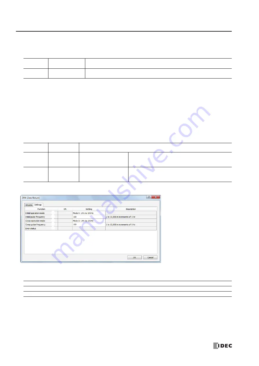
Setting tab
6. Initial operation mode
This setting selects the range of frequencies to output from the two modes.
7. Initial pulse frequency
This setting specifies the initial pulse frequency to output.
Initial operation mode 0: Set between 1 Hz and 10 kHz in increments of 1 Hz.
Initial operation mode 1: Set between 200 Hz and 100 kHz in increments of 10 Hz.
High-speed
I0, I2, I3, I5, I6, I7
An interrupt is used to read the proximity signal. The proximity signal can be read without being
affected by the user program scan.
Normal
I1, I4, I10 to I35
M0 to M1277
The information updated in the END processing is read as the proximity signal. It is affected by the
user program scan.
Storage
destination
Function
Setting
Starting
0
Pulse output ON
relay
0: Pulse output OFF
1: Pulse output ON
This relay turns on during pulse output. This relay turns off when
ZRN instruction output stops or when the proximity signal turns off
and pulse output ends.
Starting
1
Pulse output
complete relay
0: Pulse output not complete
1: Pulse output complete
This relay turns on when the proximity signal turns off and pulse
output end.
This relay turns off when ZRN instruction output starts.
10.
6.
7.
8.
9.
Initial operation mode
0: 1 Hz to 10 kHz (increments of 1 Hz)
1: 200 Hz to 100 kHz (increments of 10 Hz)
Summary of Contents for microsmart pentra
Page 1: ...FT1A SERIES FC9Y B1382 Ladder Programming Manual ...
Page 6: ...Preface 5 FT1A SMARTAXIS USER S MANUAL FT9Y B1382 ...
Page 104: ...7 DATA COMPARISON INSTRUCTIONS 7 10 FT1A SMARTAXIS USER S MANUAL FT9Y B1382 ...
Page 122: ...8 BINARY ARITHMETIC INSTRUCTIONS 8 18 FT1A SMARTAXIS USER S MANUAL FT9Y B1382 ...
Page 138: ...10 SHIFT ROTATE INSTRUCTIONS 10 12 FT1A SMARTAXIS USER S MANUAL FT9Y B1382 ...
Page 162: ...11 DATA CONVERSION INSTRUCTIONS 11 24 FT1A SMARTAXIS USER S MANUAL FT9Y B1382 ...
Page 188: ...12 CALENDAR COMPARISON INSTRUCTIONS 12 26 FT1A SMARTAXIS USER S MANUAL FT9Y B1382 ...
Page 198: ...15 REFRESH INSTRUCTIONS 15 4 FT1A SMARTAXIS USER S MANUAL FT9Y B1382 ...
Page 202: ...16 INTERRUPT CONTROL INSTRUCTIONS 16 4 FT1A SMARTAXIS USER S MANUAL FT9Y B1382 ...
Page 266: ...20 DUAL TEACHING TIMER INSTRUCTIONS 20 4 FC5A MICROSMART USER S MANUAL FC9Y B1273 ...
Page 318: ...25 USER COMMUNICATION INSTRUCTIONS 25 22 FT1A SMARTAXIS USER S MANUAL FT9Y B1382 ...


