


11: W
EEK
P
ROGRAMMER
I
NSTRUCTIONS
11-22
FC6A S
ERIES
MICROS
MART
L
ADDER
P
ROGRAMMING
M
ANUAL
FC9Y-B1726
4. S3 (source 3): The number of parameter tabs
This setting configures the number of parameter tabs.
This setting is shared in common with "To configure the dates as a fixed setting". See "4. S3 (source 3): Number of parameter
tabs" on page 11-17.
5. D1 (destination 1): Output
This setting configures the output for the results when the configured dates and the current date are compared.
This setting is shared in common with "To configure the dates as a fixed setting". See "5. D1 (destination 1): Output" on page
11-18.
6. Pulse Output
This setting configures the operation for D1 (output). This setting is applied to all parameter tabs.
This setting is shared in common with "To configure the dates as a fixed setting". See "6. Pulse Output" on page 11-18.
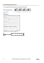
7. Data Register Allocation
Click this button to display the
Device Allocation
dialog box. As shown below, a table of the data registers and their
corresponding YEAR instruction settings is displayed on the dialog box (8). Click
Allocate Comments
(9) and you can
configure the comments for the data registers that correspond to the names of the settings.
This button is only used when indirectly specifying the settings for the YEAR instruction with data registers.
• Device Allocation dialog box
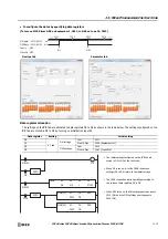
• Parameter tab
This tab configures the settings for the output. A maximum of 20 parameter tabs can be configured for 1 YEAR instruction.
If indirectly specifying the settings for the YEAR instruction with data registers, the settings configured on the parameter tabs are
stored in the data registers when the initialization input is turned on.
This setting is shared in common with "To configure the dates as a fixed setting". See "Parameter tab" on page 11-18.
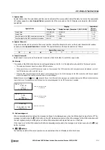
• Preview
The preview shows the ON/OFF state for the output based on the settings configured on the parameter tabs in a calendar.
This function is shared in common with "To configure the dates as a fixed setting". See "Preview" on page 11-20.
9.
8.
Summary of Contents for MICROSmart FC6A Series
Page 1: ...B 1726 7 FC6A SERIES Ladder Programming Manual ...
Page 8: ...Preface 7 FC6A SERIES MICROSMART LADDER PROGRAMMING MANUAL FC9Y B1726 ...
Page 32: ...1 OPERATION BASICS 1 20 FC6A SERIES MICROSMART LADDER PROGRAMMING MANUAL FC9Y B1726 ...
Page 96: ...3 INSTRUCTIONS REFERENCE 3 18 FC6A SERIES MICROSMART LADDER PROGRAMMING MANUAL FC9Y B1726 ...
Page 130: ...4 BASIC INSTRUCTIONS 4 34 FC6A SERIES MICROSMART LADDER PROGRAMMING MANUAL FC9Y B1726 ...
Page 192: ...9 SHIFT ROTATE INSTRUCTIONS 9 12 FC6A SERIES MICROSMART LADDER PROGRAMMING MANUAL FC9Y B1726 ...
Page 272: ...12 DISPLAY INSTRUCTIONS 12 24 FC6A SERIES MICROSMART LADDER PROGRAMMING MANUAL FC9Y B1726 ...
Page 284: ...14 REFRESH INSTRUCTIONS 14 6 FC6A SERIES MICROSMART LADDER PROGRAMMING MANUAL FC9Y B1726 ...
Page 502: ...25 DATA LOG INSTRUCTIONS 25 22 FC6A SERIES MICROSMART LADDER PROGRAMMING MANUAL FC9Y B1726 ...
Page 546: ...26 SCRIPT 26 44 FC6A SERIES MICROSMART LADDER PROGRAMMING MANUAL FC9Y B1726 ...
Page 598: ...APPENDIX A 14 FC6A SERIES MICROSMART LADDER PROGRAMMING MANUAL FC9Y B1726 ...


