17: U
SER
C
OMMUNICATION
I
NSTRUCTIONS
« FC4A M
ICRO
S
MART
U
SER
’
S
M
ANUAL
»
17-23
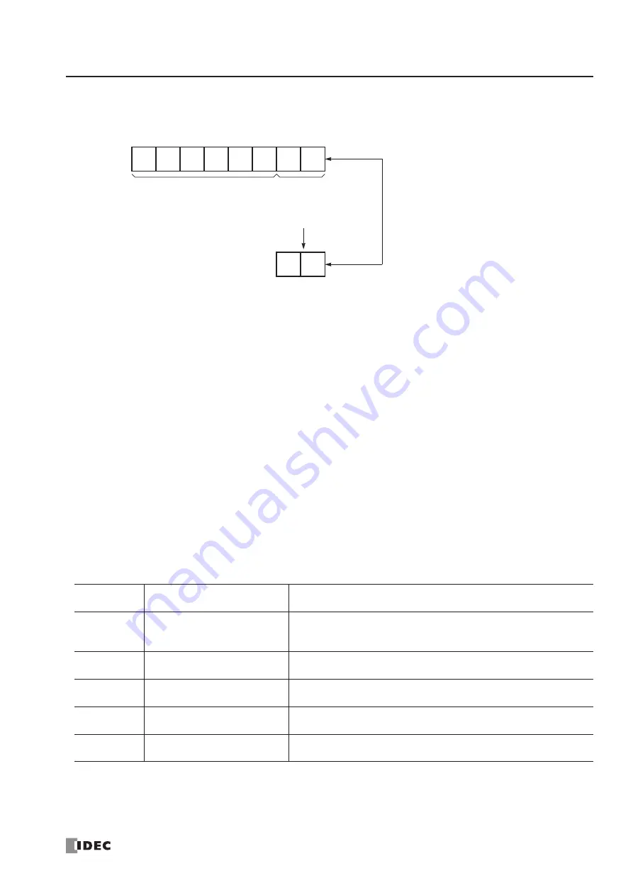
Example 2:
BCC is calculated for the first byte through the sixth byte using the ADD format, converted in binary to
ASCII, and compared with the BCC code appended to the seventh and eighth bytes of the incoming data.
Receive Completion Output
Designate an output, Q0 through Q107, or internal relay, M0 through M1277, as an operand for the receive completion
output.
When the start input for a RXD instruction is turned on, preparation for receiving data is initiated, followed by data con-
version and storage. When a sequence of all data receive operation is complete, the designated output or internal relay is
turned on.
Conditions for Completion of Receiving Data
After starting to receive data, the RXD instruction can be completed in three ways:
•
When an end delimiter is received (except when a BCC exists immediately after the end delimiter).
•
When receive timeout occurs.
•
When a specified byte count of data has been received.
Data receiving is completed when one of the above three conditions is met. To abort a RXD instruction, use the user com-
munication receive instruction cancel flag M8022 or M8023. See page 17-24.
Receive Status
Designate a data register, D0 through D1298 or D2000 through D7998, as an operand to store the receive status informa-
tion including a receive status code and a user communication error code.
Receive Status Code
If the receive status code is other than shown above, an error of receive instruction is suspected. See User Communication
Error Code on page 17-27.
Receive
Status Code
Status
Description
16
Preparing data receive
From turning on the star t input for a RXD instruction to read the
receive format, until the RXD instruction is enabled by an END pro-
cessing
32
Receiving data
From enabling the RXD instruction by an END processing, until incom-
ing data is received
48
Data receive complete
From receiving incoming data, until the received data is conver ted and
stored in data registers according to the receive format
64
Receive instruction complete
All data receive operation is completed and the next data receive is
made possible
128
User communication receive
instruction cancel flag active
RXD instructions are cancelled by special internal relay M8022 or
M8023
“1”
(31h)
“2”
(32h)
BCC Calculation Range
“3”
(33h)
“4”
(34h)
Incoming Data
“5”
(35h)
“6”
(36h)
“0”
(30h)
“7”
(37h)
BCC
31h + 32h + 33h + 34h + 35h + 36h = 135h
“3”
(33h)
“5”
(35h)
BCC Calculation Result
Binar y to ASCII Conversion
Comparison result is false.
Error code 9 is stored in the receive
status data register.
Summary of Contents for FC4A-C10R2
Page 1: ...FC4A SERIES Micro Programmable Logic Controller User s Manual FC9Y B812 ...
Page 6: ...PREFACE 4 FC4A MICROSMART USER S MANUAL ...
Page 94: ...2 MODULE SPECIFICATIONS 2 74 FC4A MICROSMART USER S MANUAL ...
Page 184: ...6 ALLOCATION NUMBERS 6 20 FC4A MICROSMART USER S MANUAL ...
Page 218: ...8 ADVANCED INSTRUCTIONS 8 8 FC4A MICROSMART USER S MANUAL ...
Page 240: ...11 BINARY ARITHMETIC INSTRUCTIONS 11 8 FC4A MICROSMART USER S MANUAL ...
Page 244: ...12 BOOLEAN COMPUTATION INSTRUCTIONS 12 4 FC4A MICROSMART USER S MANUAL ...
Page 252: ...13 SHIFT ROTATE INSTRUCTIONS 13 8 FC4A MICROSMART USER S MANUAL ...
Page 274: ...15 WEEK PROGRAMMER INSTRUCTIONS 15 8 FC4A MICROSMART USER S MANUAL ...
Page 378: ...22 DUAL TEACHING TIMER INSTRUCTIONS 22 4 FC4A MICROSMART USER S MANUAL ...
Page 386: ...23 INTELLIGENT MODULE ACCESS INSTRUCTIONS 23 8 FC4A MICROSMART USER S MANUAL ...
Page 408: ...24 ANALOG I O CONTROL 24 22 FC4A MICROSMART USER S MANUAL ...
Page 426: ...26 COMPUTER LINK COMMUNICATION 26 6 FC4A MICROSMART USER S MANUAL ...


