7: B
ASIC
I
NSTRUCTIONS
« FC4A M
ICRO
S
MART
U
SER
’
S
M
ANUAL
»
7-25
JMP (Jump)
and JEND (Jump End)
The JMP (jump) instruction is usually used in combination with the JEND (jump end) instruction. At the end of a program,
the JMP instruction can also be used with the END instruction, instead of the JEND instruction.
These instructions are used to proceed through the portion of the program between the JMP and the JEND
without
pro-
cessing. This is similar to the MCS/MCR instructions, except that the portion of the program between the MCS and MCR
instruction
is
executed.
When the operation result immediately before the JMP instruction is on, the JMP is valid and the program is
not
executed.
When the operation result immediately before the JMP instruction is off, the JMP is invalid and the program is executed.
When the input condition to the JMP instruction is on and the JMP is executed, other instructions between the JMP and
JEND are executed as follows:
Input conditions cannot be set for the JEND instruction.
More than one JMP instruction can be used with one JEND instruction.
Corresponding JMP/JEND instructions cannot be nested within another pair of corresponding JMP/JEND instructions.
Instruction
Status
SOTU
Rising edges (ON pulses) are not detected.
SOTD
Falling edges (OFF pulses) are not detected.
OUT and OUTN
All are held in current status.
SET and RST
All are held in current status.
TML, TIM, TMH, and TMS
Current values are held.
Timeout statuses are held.
CNT, CDP, and CUD
Current values are held.
Pulse inputs are turned off.
Countout statuses are held.
SFR and SFRN
Shift register bit statuses are held.
Pulse inputs are turned off.
The output from the last bit is held.
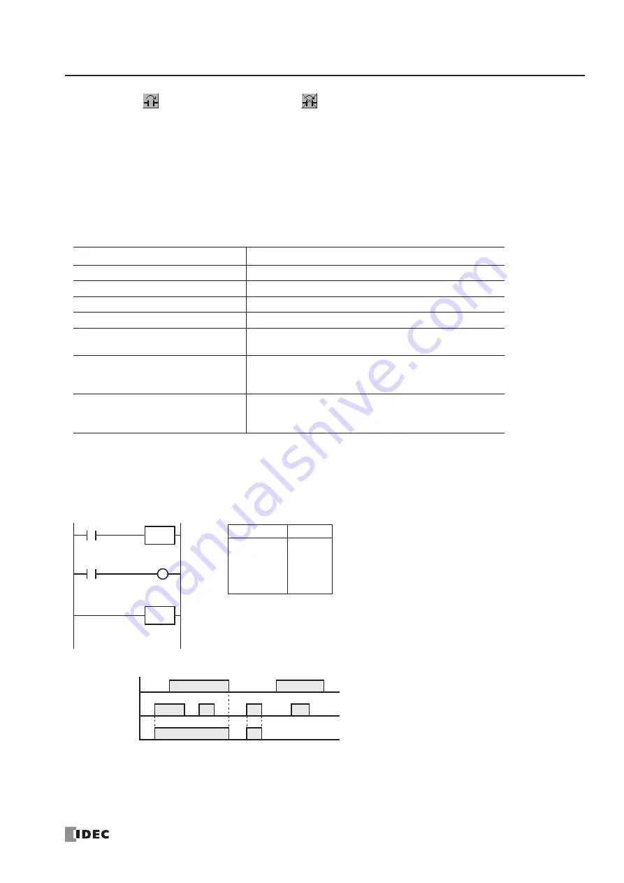
Ladder Diagram
I0
I1
Input I0
ON
OFF
Input I1
ON
OFF
Output Q0
ON
OFF
Timing Chart
JMP
JEND
When input I0 is on, JMP is executed so that the subsequent
output status is held.
When input I0 is off, JMP is not executed so that the following
program is executed according to the actual input statuses.
Instruction
Data
LOD
JMP
LOD
OUT
JEND
I0
I1
Q0
Program List
Q0
Summary of Contents for FC4A-C10R2
Page 1: ...FC4A SERIES Micro Programmable Logic Controller User s Manual FC9Y B812 ...
Page 6: ...PREFACE 4 FC4A MICROSMART USER S MANUAL ...
Page 94: ...2 MODULE SPECIFICATIONS 2 74 FC4A MICROSMART USER S MANUAL ...
Page 184: ...6 ALLOCATION NUMBERS 6 20 FC4A MICROSMART USER S MANUAL ...
Page 218: ...8 ADVANCED INSTRUCTIONS 8 8 FC4A MICROSMART USER S MANUAL ...
Page 240: ...11 BINARY ARITHMETIC INSTRUCTIONS 11 8 FC4A MICROSMART USER S MANUAL ...
Page 244: ...12 BOOLEAN COMPUTATION INSTRUCTIONS 12 4 FC4A MICROSMART USER S MANUAL ...
Page 252: ...13 SHIFT ROTATE INSTRUCTIONS 13 8 FC4A MICROSMART USER S MANUAL ...
Page 274: ...15 WEEK PROGRAMMER INSTRUCTIONS 15 8 FC4A MICROSMART USER S MANUAL ...
Page 378: ...22 DUAL TEACHING TIMER INSTRUCTIONS 22 4 FC4A MICROSMART USER S MANUAL ...
Page 386: ...23 INTELLIGENT MODULE ACCESS INSTRUCTIONS 23 8 FC4A MICROSMART USER S MANUAL ...
Page 408: ...24 ANALOG I O CONTROL 24 22 FC4A MICROSMART USER S MANUAL ...
Page 426: ...26 COMPUTER LINK COMMUNICATION 26 6 FC4A MICROSMART USER S MANUAL ...


