Pictograms and symbols
4
Service Unit iMAT 33
Pos : 1 /Beko Tec hnisc he Dokumentati on/Ü bersc hriften/1/Pi ktogramme und Symbol e @ 1\mod_1290773595840_15098.doc x @ 20525 @ 1 @ 1
1
Pictograms and symbols
Pos : 2 /Beko Tec hnisc he Dokumentati on/Pi ktogramme/Anl eitung beac hten blau @ 0\mod_1213268300255_15098.doc x @ 15193 @ @ 1
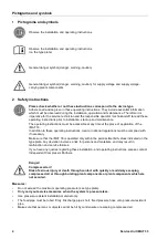
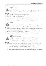
Observe the installation and operating instructions
Pos : 3 /Beko Tec hnisc he Dokumentati on/Pi ktogramme/Anl eitung beac hten s/w T ypensc hild @ 1\mod_1290772180142_15098.doc x @ 20492 @ @ 1
Observe the installation and operating instructions
(on the type plate)
Pos : 4 /Beko Tec hnisc he Dokumentati on/Pi ktogramme/Gefahr Warnung Vorsic ht s/w @ 0\mod_1213265685174_15098.doc x @ 15189 @ @ 1
General danger symbol (danger, warning, caution)
Pos : 5 /Beko Tec hnisc he Dokumentati on/Pi ktogramme/G+W+ V N etz spannung s /w @ 0\mod_1213266193701_15098.doc x @ 15191 @ @ 1
General danger symbol (danger, warning, caution) for supply voltage and supply voltage-
carrying plants components
Pos : 6 /Beko Tec hnisc he Dokumentati on/Ü bersc hriften/1/Sic herheits hinweise @ 0\mod_1183637609261_15098.doc x @ 15102 @ 1 @ 1
2
Safety instructions
Pos : 7 /Beko Tec hnisc he Dokumentati on/Sic herheit/Hi nweis Anlei tung mit D oc Var als Fir menname @ 8\mod_1405062780358_15098.doc x @ 41099 @ @ 1
Please check whether or not these instructions correspond to the device type.
Adhere to all advice given in these operating instructions. They include essential information
which must be observed during the installation, operation and maintenance. Therefore it is
imperative for the service technician and the responsible operator / technical staff to read these
operating instructions prior to installation, start-up and maintenance.
The operating instructions must be accessible at any time at the place of application of the
iMAT 33.
In addition to these operating instructions, local or national regulations must be complied with,
if necessary.
Make sure that the iMAT 33 is operated only within the permissible limit values indicated on the
type plate. Any deviation involves a risk for persons and materials, and may result in
malfunction and service failures.
If you have any queries regarding these installation- and operating instructions, please contact
Independent Compressor Partners.
Pos : 8 /Beko Tec hnisc he Dokumentati on/Sic herheit/Gefahr Druc kluft @ 0\mod_1184148143854_15098.doc x @ 15121 @ @ 1
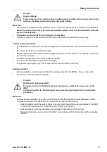
Danger!
Compressed air!
Risk of serious injury or death through contact with quickly or suddenly escaping
compressed air or through bursting plant components or plant components which are
not secured.
Pos : 9 /Beko Tec hnisc he Dokumentati on/Sic herheit/M aß nahmen Dr uc kl uft BM @ 0\mod_1184148284291_15098.doc x @ 15123 @ @ 1
Measures:
•
Do not exceed the maximum operating pressure (see type plate).
•
Only carry out service measures when the system is pressure less.
•
Use pressure-resistant installation material only.
•
The feed pipe must be tubed firmly. Discharge pipe: short, fixed pressure hose onto pressure-resistant
pipe.
•
Make sure that persons or objects cannot be hit by condensate or escaping compressed air.
Pos : 10 /Beko T ec hnis che D okumentati on/Sic her hei t/Gefahr Netzs pannung 1 s/w @ 0\mod_1184148186948_15098.doc x @ 15122 @ @ 1
Summary of Contents for Service Unit iMAT 33
Page 2: ...2 Service Unit iMAT 33...


