


Electrical installation
iMAT 31IFBI-24VDC
13
Pos : 42 /Beko T ec hnis che D okumentati on/Übersc hriften/1/Elektrische Install ati on @ 0\mod_1183638507355_15098.doc x @ 15116 @ 1 @ 1
10 Electrical installation
Pos : 43 /Beko T ec hnis che D okumentati on/Installati on/BEKOMAT /El ektrInstallation Hi nweis e BM IF @ 2\mod_1294907400904_15098.doc x @ 20827 @ @ 1
Note:
1.
Only use a protective extra-low-voltage (PELV) in
accordance with IEC 60364-4-41.
2. Carry out installation in accordance with
VDE 0100 / IEC 60364.
3. Observe the terminal assignment.
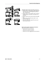
4. Unscrew the screw (1) and remove upper part of
the cover (2).
5. Unscrew the threaded cable connection (3) (if
there is one), remove the plug and lead the cable
(4) for the supply voltage through.
6. Connect the cable (4) with the terminals (5).
7. Install the cables as shown (see also terminal
assignment in the following text).
8. Tighten the threaded cable connection (3) with a
slightly sealing effect.
9. Put on the upper part of the cover (2) and tighten
the screw (1) fingertight.
10.Between the Gnd connection and the piping, a
potential difference is not admissible. If required,
potential equalization in accordance with
VDE 0100 / IEC 60364 must be provided for.
Pos : 44 /Beko T ec hnis che D okumentati on/Installati on/BEKOMAT /Kl emmenbel egung BM 3xU IF @ 9\mod_1409833267739_15098.doc x @ 42000 @ @ 1
Summary of Contents for IMAT 31IFBI-24VDC
Page 21: ...iMAT 31IFBI 24VDC 21 ...
Page 22: ...22 iMAT 31IFBI 24VDC ...
Page 23: ...iMAT 31IFBI 24VDC 23 ...


