ICP DAS PMC-523x/PMC-224x/PMD Series User Manual
63
i.
In the “Baudrate” field, select the Baudrate from the dropdown list, the
Baudrate of PMC/PMD and HMI or SCADA have to be set the same.
ii.
In the “Parity” and “Stop bits” fields, set up the Parity and Stop bits.
The Parity and Stop bits of PMC/PMD and HMI or SCADA have to
be set the same.
iii.
After all settings are completed, click “Save” button to save the
changes.
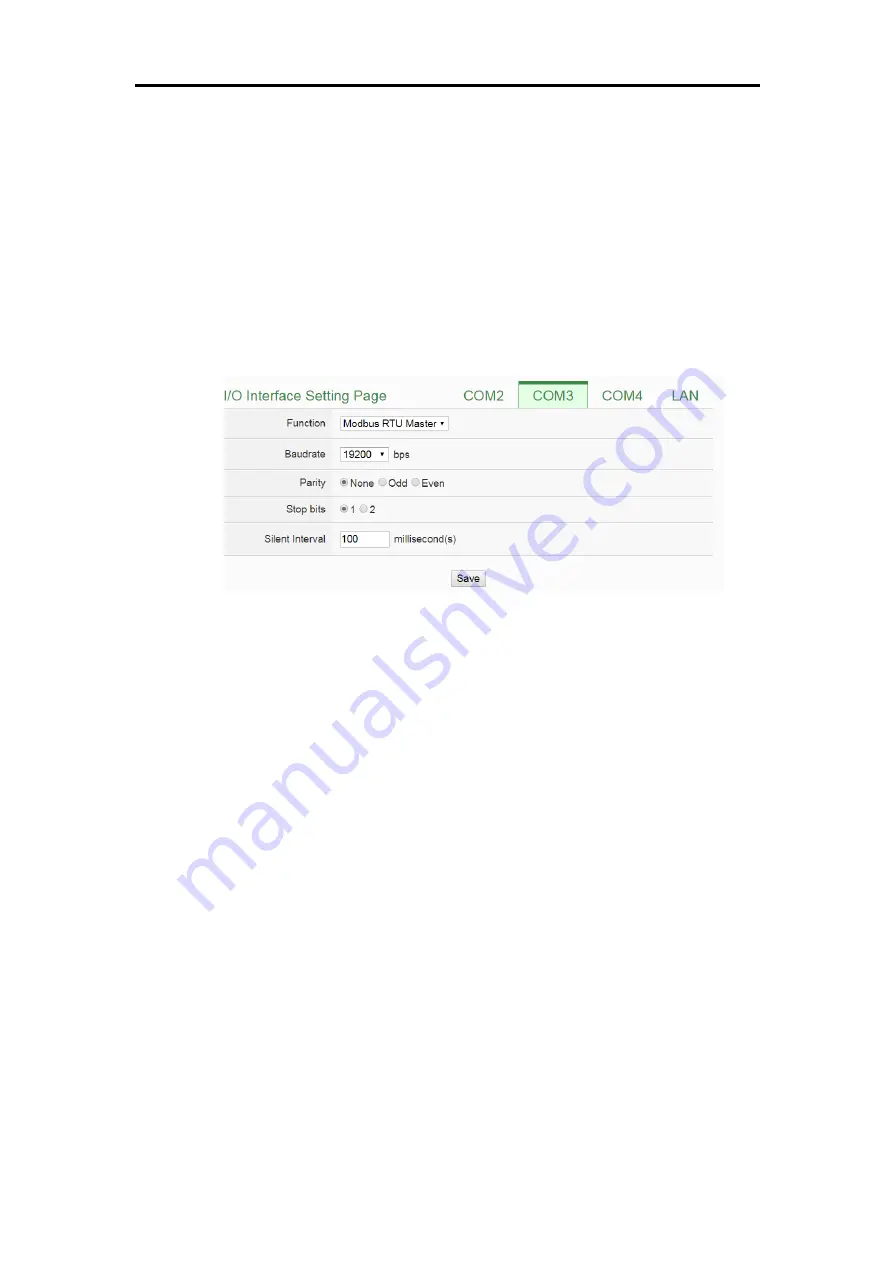
Connect to Modbus RTU slave device via COM Port.
Figure6-19 :
Function setting to connect to Modbus RTU slave device
The settings steps are as below:
i.
In the “Baudrate” field, select the Baudrate from the dropdown list, the
Baudrate of PMC/PMD and Modbus RTU slave device have to be set
the same.
ii.
In the “Parity” and “Stop bits” fields, set up the Parity and Stop bits.
The Parity and Stop bits of PMC/PMD and Modbus RTU slave device
have to be set the same.
iii.
In the “Silent Interval” field, input the time interval between successive
sending of commands from the PMC/PMD to the Modbus RTU slave
device, the unit will be millisecond (ms).
Please Note: After the “Baudrate” is selected, the system will
automatically generate a proper value in the “Silent Interval” field.
For each Modbus RTU Slave device has different Modbus command
process capability, the response time for sending result from Modbus
RTU Slave device to PMC/PMD might be different. The user can
adjust this value to most appropriate time interval, such as: extend
this value to make sure every Modbus RTU Slave device connected to
the PMC/PMD has enough time to process the Modbus command, or
Summary of Contents for PMC-523 Series
Page 1: ...ICP DAS PMC 523x PMC 224x PMD Power Meter Concentrator Series User Manual Version 3 2 4...
Page 165: ...ICP DAS PMC 523x PMC 224x PMD Series User Manual 150 Figure9 14 The Import of MQTT Topic...
Page 205: ...ICP DAS PMC 523x PMC 224x PMD Series User Manual 190 Figure10 53 PUE Setting Page 2...


