background image


Getting Started: I-8437-80/8837-80/8417/8817, Jul 2020 V4.0        48 

2.5.2


Running the Example Program 

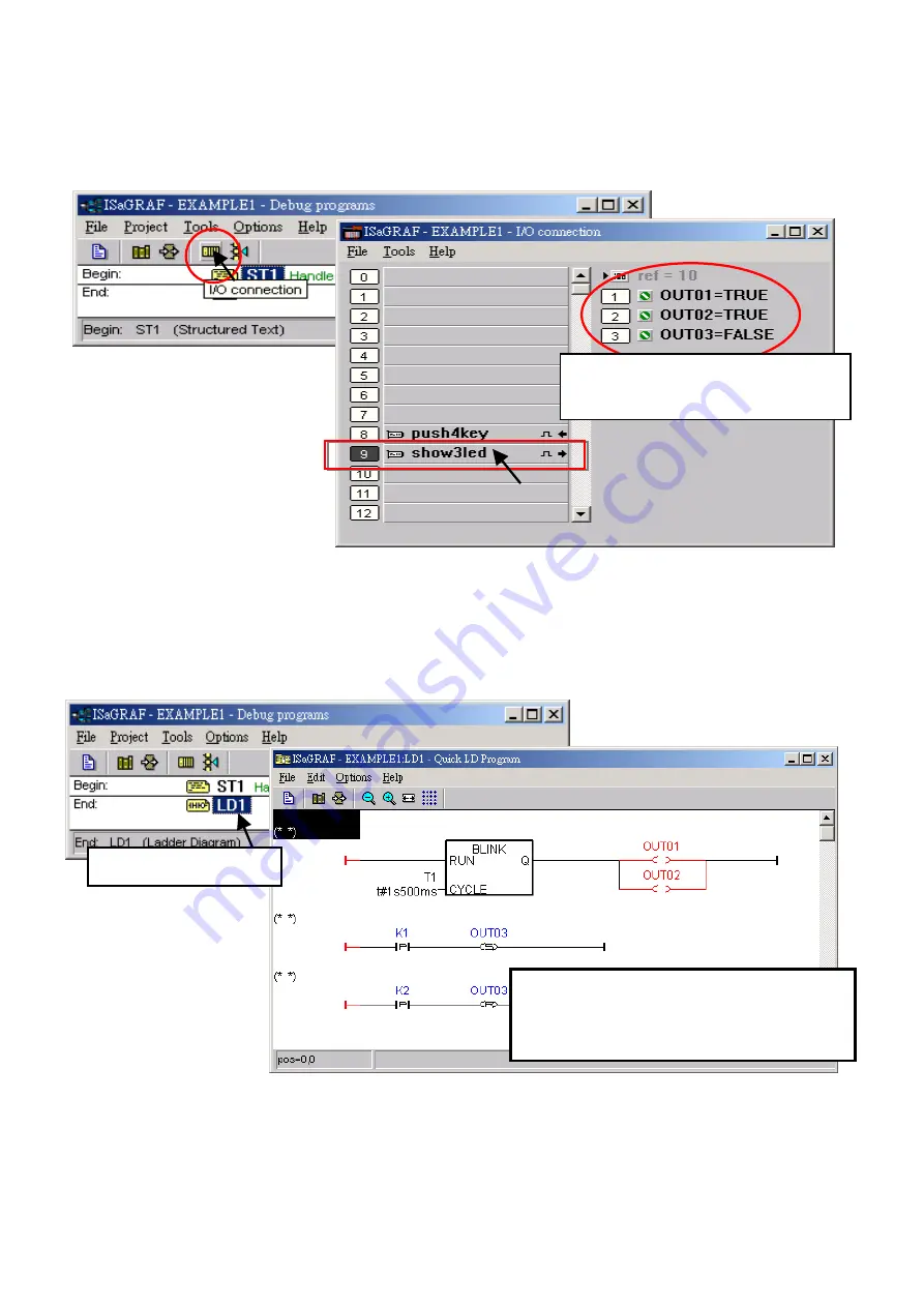
The user can observe the I/O status while the project is running. The way is to click the "I/O 
Connection" button in the ISaGRAF “Debug Programs” window and then you can see the status 
of I/O variables in the "I/O Connection" window. 


Another helpful window for observing the running status of the LD program is the "Quick LD 
Program" window. You can try to press one of the first two buttons (or click K1 / K2) on the front 
panel of the PAC, then to view the status of “OUT03”.  


Though there are numerous steps involved in creating and downloading an ISaGRAF program, 
each step is quick and easy to accomplish. ISaGRAF provides a powerful and flexible software 
environment to develop the PAC control system. 


In the example, OUT01 and 
OUT02 is blinking (TURE/FALSE). 

Buttons on the PAC panel

Click button1 (K1), L3 (OUT3) is lighted up. 
Click button2 (K2), L3 (OUT3) is turn out. 

Double-click on LD1. 


Summary of Contents for ISaGRAF I-8437-80

Page 1: ...s product ICP DAS CO LTD reserves the right to change this manual at any time without notice ICP DAS CO LTD constantly strives to provide our customers with the most reliable and accurate information...

Page 2: ...Revision History This chapter provides revision history information to this document The table below shows the revision history Revision Date Description V2 0 Jul 2020 Update URLs to the new website...

Page 3: ...6 Motion Control 12 1 7 Modbus Converter of I 7000 I 87K I O 13 1 8 Modbus Master 14 1 9 Data Exchange through Ethernet RS 485 15 1 10 Active Control Data and I O Acquisition Data Reporting System 15...

Page 4: ...hapter 3 Hardware System Setting 49 3 1 Setting the NET ID for the I 8xx7 49 3 2 Connecting PC to the I 8xx7 s COM1 50 3 3 Connecting PC to I 8417 8817 s COM2 51 3 4 Connecting PC to Several I 8417 88...

Page 5: ...gnment of Communication Ports 70 3 20 Dimension 71 Appendix 73 A ISaGRAF User Manual Demo Program FAQ 73 A 1 The Download Page for ISaGRAF Resource 73 A 2 Using Modbus TCP IP protocol to control ISaGR...

Page 6: ...m 425 Related Products Industrial Ethernet Switch http www icpdas com en product guide Industrial__Communication Ethernet__Communi cation Ethernet__Switch RS 232 to RS 422 485 Converter http www icpda...

Page 7: ...ection Guide The I 8xx7 series PAC supports the I 8K I 87K I O modules and RS 485 remote I O modules modules Please refer to ICP DAS website http www icpdas com en product guide Remote__I_O__Module__a...

Page 8: ...Getting Started I 8437 80 8837 80 8417 8817 Jul 2020 V4 0 8 Specifications I 8437 80 8837 80 I 8417 8817...

Page 9: ...837 80 8417 8817 Jul 2020 V4 0 9 Note I 8x37 has already been phased out please select compatible I 8x37 80 ISaGRAF Download Center Refer to Data Sheet http www icpdas com en download index php nation...

Page 10: ...dvanced I 8xx7 ISaGRAF based iPAC Features Support Dual Ethernet 10 100 Mbps 768K memory for running program 256K more than I 8437 80 8837 80 Built in 512K Battery backup SRAM Support sending E mail w...

Page 11: ...ing Started I 8437 80 8837 80 8437 8837 8417 8817 Jul 2020 V2 0 11 1 3 Redundant Bus7000 I 8437 80 8837 80 1 4 SMS Short Message Service More at https www icpdas com en faq index php kind 280 751 FAQ...

Page 12: ...12 1 5 Download Monitoring Via Modem_Link 1 6 Motion Control I 8091 2 axes I 8090 3 axes Encoder I 8417 8817 8437 80 8837 80 One I 8091 can control 2 axis X Y plane or 2 axes independent Two I 8091 ca...

Page 13: ...17 8817 Jul 2020 V2 0 13 1 7 Modbus Converter of I 7000 I 87K I O I 8417 8817 can be a Modbus RTU serial converter of I 7000 I 87K series I O modules I 8437 80 8837 80 can be a Modbus RTU serial TCP I...

Page 14: ...4 1 8 Modbus Master Up to 2 COM Ports COM1 COM3 COM4 and COM5 in multi serial port board can support Modbus RTU Master or ASCII Master Protocol to connect to other Modbus Slave devices NOTE COM5 to CO...

Page 15: ...l 2020 V2 0 15 1 9 Data Exchange through Ethernet RS 485 1 10 Active Control Data and I O Acquisition Data Reporting System More at https www icpdas com en faq index php kind 280 751 FAQ 065 PAC to PA...

Page 16: ...duct has been phased out users can choose ZT 2000 series product ISaGRAF PAC plus ZB 2550P and ZB 2551P RS 232 RS 485 Converters can apply wireless communication reduce the wiring cost and achieve the...

Page 17: ...omputer operating systems must be installed on the target computer system before you can install the ISaGRAF Workbench software program Windows 95 Windows 98 Windows 2000 Windows NT Version 3 51 or Wi...

Page 18: ...cannot find the dongle well Please reset your PC and then check the Help About again If it still displays Maximum number of IO variables 32 the driver may not be installed well Please do the followin...

Page 19: ...rtcut property 2 1 3 Important Notice for Window NT Users If your computer is using the Windows NT operating system you will need to add one line to the isa ini file in the ISaGRAF Workbench EXE subdi...

Page 20: ...the setup restrictions How to disable UAC User Account Control The UAC User Account Control setting requires administrator level permission 1 From the Start menu choose Control Panel User Accounts an...

Page 21: ...8837 80 8417 8817 Jul 2020 V4 0 21 Windows 7 Move the slider down to Never Notify and then click on OK 3 Reboot your computer to apply the change 4 After rebooting please refer to section 2 1 Install...

Page 22: ...x64 msu to install Windows Virtual PC 4 Reboot your computer 5 After rebooting click on Star All Programs Windows Virtual PC and then click Windows XP Mode 6 Follow the instructions in the wizard to c...

Page 23: ...io_lib zip http www icpdas com en download show php num 368 The ICP DAS Utilities for ISaGRAF consists of 3 major items I O libraries For all ISaGRAF PAC Modem_Link utility Auto scan I O utility Note...

Page 24: ...o programs One is ST program and the other is LD program Variables declaration Name Type Attribute Description INIT Boolean Internal Initial value at TRUE TRUE means 1st scan cycle OUT01 Boolean Outpu...

Page 25: ...3 1 Open ISaGRAF Project Management Click on the Windows Start Programs ISaGRAF 3 4 Projects as shown below 2 3 2 Creating an ISaGRAF User s Group Click on the Select Program Group to open the Project...

Page 26: ...r this group 2 3 3 Creating a New ISaGRAF Project To start a new ISaGRAF project click on the Create New Project button and then enter the name for the project you can then enter additional informatio...

Page 27: ...To begin this process click on the Dictionary button 2 Click on the Booleans tab to declare the Boolean 3 Double click the first blank row below the Booleans tab to open the Boolean Variable window Pl...

Page 28: ...ed Also you can double click the variable name to change the setting Quick Declaration There are three outputs used in this example program named OUT01 OUT02 and OUT03 ISaGRAF provides a quick and eas...

Page 29: ...8817 Jul 2020 V4 0 29 All three outputs will be immediately added to the Global Boolean window Please click Save button to save them Use the same method as former to create another 2 variables K1 K2 h...

Page 30: ...le used in this example program 1 Click the Timers tab in the setup screen and double click on the colored area 2 Enter the Name as T1 and set the Attributes to Internal 3 Set the Initial Value to T 8...

Page 31: ...T variable the Language as ST Structured Text and then Style as Begin Main program Then click on OK Now we have one program inside this project ISaGRAF will run every program one time in each PLC scan...

Page 32: ...gram window will appear Enter the Name as LD1 Next click on the Language scroll button and select Quick LD Ladder Diagram and make sure the Style is set to End Main Program Also add any desired text i...

Page 33: ...on Insert Rung Insert Rung means to insert a basic LD rung just above the current position Or you may just click on the F2 Contact on the Left button and the following will appear within the Quick LD...

Page 34: ...sociated variable constant to each item Double click anywhere inside the block and the Function Block assignment window appears Select the BLINK type function block and press OK To learn how the BLINK...

Page 35: ...move your cursor to the left of the parameter CYCLE of the BLINK block Double click on it select Timer and then double click on variable name T1 Move your cursor to the coil Double click on it select...

Page 36: ...V4 0 36 Click on coil button to create one another coil below the OUT01 and then assign a Boolean name OUT02 to it Then we have the below window To insert the second LD rung move the cursor to be unde...

Page 37: ...to assign name K1 and OUT03 to the correct position Move the cursor to K1 and then click on Coil contact type several times to set the type of K1 to P and then set the type of OUT03 to S By the same...

Page 38: ...and OUT03 and input variables i e K1 K2 These input output variables should be mapped to I O channels or function keys on the PAC before they can work To do that click on I O connection to get into t...

Page 39: ...0 39 Then we have this window To map input variables K1 K2 to the channel No 1 2 of the push4key double click on the channel 1 and then click on Connect Then click on Connect again to connect channel...

Page 40: ...used in the I 8xx7 PAC You can use slot No 8 and above for additional functionality as illustrated by the example program 2 All of the variables with Input and Output attribute MUST be connected throu...

Page 41: ...Code for Intel option To begin the compilation process click Compiler Options from the Make menu Make sure that three items illustrated in the figure below are selected and then click the OK button No...

Page 42: ...button to review the error messages Return to the project and correct the errors as outlined in the error message window 2 4 2 Simulating the LD Project If the compilation is Ok you may simulate the...

Page 43: ...g the Simulation Program After double clicking on LD1 in the ISaGRAF Debug Programs window you can see OUT1 and OUT2 is blinking every 1 5 seconds Users can adjust the value of the T1 variable during...

Page 44: ...the T1 as t 500ms in the Write Timer Variable dialog box and click Write to set the value Now we are going to simulate the K1 K2 input Right click on the K1 button will light up the OUT03 Also try to...

Page 45: ...that can be used to connect both COM1 or COM2 of the PC and COM1 of the PAC Click the Link Setup button in the ISaGRAF Programs window In the PC PLC Link parameters window set the communication parame...

Page 46: ...ween the PC and the PAC is not functioning The most common causes for this problem is either the serial port cable not being properly configured or the development PC s serial port communications DO N...

Page 47: ...de for Intel in the Download dialog box Click the Download button to download the project to the PAC Then a progress bar will appear in the ISaGRAF Debugger window to show the downloading progress If...

Page 48: ...of the LD program is the Quick LD Program window You can try to press one of the first two buttons or click K1 K2 on the front panel of the PAC then to view the status of OUT03 Though there are numero...

Page 49: ...t the DIP2 to ON If Net ID 03 20 21 3 set the DIP 1 2 to ON If Net ID 04 22 4 please setup the DIP 3 to ON If Net ID 05 20 22 5 set the DIP 1 3 to ON If Net ID FE 16 254 10 21 22 23 24 25 26 27 254 se...

Page 50: ...1 that is 19200 baud rate 8 data bits no stop bits and one parity bit The following figure shows commonly used RS 232 pin assignments When ISaGRAF doing RS 232 communications only the RxD TxD and GND...

Page 51: ...an RS 485 network In this way the PC can download ISaGRAF project to each PAC via the RS 485 network Up to 255 I 8xx7 can be connected each other We do not recommend connecting so many PACs if not nec...

Page 52: ...splay Notice If there is no operation within one minute buttons will not work L1 turn off please restart the PAC as described above SEL 0 is used to set the baud rate of first Slave port i e COM1 whil...

Page 53: ...rst two buttons and power on the PAC until the setting mode appears on the LED display First press the Up or Dn button until SEL 2 Select 2 appears and press the OK button You can see dEL n show in th...

Page 54: ...ers correctly for successfully downloading the ISaGRAF project to the PAC over the network Refer to section 3 9 to set IP Mask and Gateway address First open an ISaGRAF project on PC and click the Lin...

Page 55: ...OM2 RS 485 I 8437 80 8837 80 supports COM1 RS 232 and COM3 RS 232 485 Note that the default setting of the COM3 is non Modbus Slave Port also refer to Section 3 5 to change the setting I 8437 80 8837...

Page 56: ...PC and a PAC is functional through a RS 232 cable Refer Section 3 11 step4 to modify the 7188xw ini file if using other COM port e g COM5 4 Launch the Command Prompt window and type ipconfig to displ...

Page 57: ...der named 8000 in the hard drive e g c 8000 2 Copy 7188xw exe 7188xw ini 7188xw f4 isa exe autoexec bat and 8k050408 img from the driver folder to the 8000 folder 3 To check that the serial connection...

Page 58: ...4 isa exe isa_data exe autoexec bat and 8k050408 img from the driver folder to the 8000 folder 3 To check that the serial connection e g COM1 between a PC and a PAC is functional through a RS 232 cabl...

Page 59: ...ot system isa_data exe autoexec bat isa exe 8k050408 img Wait about 60 seconds to update ISaGRAF system and DO NOT REMOVE THE POWER 9 Type dir to make sure autoexec bat and isa exe are well burned 10...

Page 60: ...ISaGRAF service Backing Up an ISaGRAF Project 1 Open the ISaGRAF Project Management window On the Tools menu point to Archive and then click Projects 2 In the Archive Projects window click Browse to d...

Page 61: ...cts window and restore the ISaGRAF project from the backup file 1 In the Archive section choose the project you want to restore 2 Click Restore to restore the file to the ISaGRAF Workbench 3 13 Pin as...

Page 62: ...ake sure the hardware connection is correct 2 Configure I 87K I O modules with I 87Kn or RU 87Pn 3 Search and configure the modules one by one 4 Set the module as the INIT mode and power it up Step 1...

Page 63: ...he GND pin and power on the module This status also called INIT mode o To initialize an I 87K module set the DIP switch on the I 87K4 5 8 9 For example adjust the Dip 2 to ON and restart the I 87Kn to...

Page 64: ...8417 8817 Jul 2020 V2 0 64 2 Click Start Search button to begin search module Step 4 Click Searched module ID and give the new configuration Click when it is searched and double click module number t...

Page 65: ...tting to save If the I 7000 module is not configured in INIT mode the message window will be shown Refer to Step2 and set the module again After completing the settings disconnect the INIT and the GND...

Page 66: ...below the COM3 is used When using the COM4 port to connect I O modules the I 7520R RS 232 to RS 485 Converter is needed to connect both the PAC and remote I O modules One I 8xx7 can connect up to 64 r...

Page 67: ...ing COM3 RS 485 one iP 8x47 can connect to several devices Note Each device on the same RS 485 network must has a unique address i e NET ID 1 to 255 and the same baud rate settings When using COM1 COM...

Page 68: ...num 333 2 Touch Panel Monitor User Manual http www icpdas com en download show php num 432 Note Touch 500 series products have been phased out visit the website for new information about products Touc...

Page 69: ...es can only be plugged in slot 0 to 3 of the I 8xx7 the rest of the slots are not available Thus only COM5 to 20 can be added a total of 16 COM ports The following ISaGRAF functions can be used to rea...

Page 70: ...Getting Started I 8437 80 8837 80 8417 8817 Jul 2020 V2 0 70 3 19 Pin Assignment of Communication Ports...

Page 71: ...Getting Started I 8437 80 8837 80 8417 8817 Jul 2020 V2 0 71 3 20 Dimension 8 Slots...

Page 72: ...Getting Started I 8437 80 8837 80 8417 8817 Jul 2020 V2 0 72 4 Slots...

Page 73: ...ls and demo programs are all on the website You can follow the steps below to view the latest information and FAQ on the ISaGRAF webpage A 1 The Download Page for ISaGRAF Resource Click the Download C...

Page 74: ...7 Jul 2020 V2 0 74 Also type the ICP DAS s web address http www icpdas com in the browser Click the SUPPORT and Download Center to go to the webpage Type ISaGRAF in the Keywords field and click Search...

Page 75: ...en product guide Software Development__Tools ISaGRAF Refer to the following ISaGRAF FAQ 1 VB net 2005 Demo program using Modbus TCP IP protocol to control ISaGRAF PACs Please refer to the website htt...

Page 76: ...al designed for thermocouple inputs The innovative design makes the thermocouple measurement more accurate than the previous design 2 It supports voltage and current inputs The voltage input ranges ca...

Page 77: ...ftware__Support 768 RU 87Pn is designed to be used in harsh and noisy environment so the hardware is manufactured with wide power input range 10 30 VDC and operating temperature 25 75 C It simplifies...

Page 78: ...asy Maintenance and Diagnostic The basic configurations includes station number baud rate are set by the Rotary and DIP switch The operator can use only one screwdriver to set the RU 87Pn And there ar...

Reviews: