
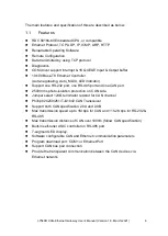

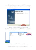

I-7540D CAN-Ethernet Gateway User’s Manual (Version 1.8, March/2021)
14
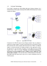
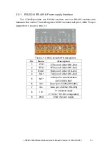
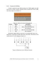
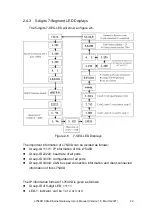
2.2.2 Connect to CAN Bus
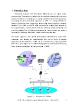
In order to provide an easy CAN bus wiring, the I-7540D supplies one CAN
port with two CAN bus connector interfaces. Each connecter built on the I-7540D
looks like as figure 2-3 and table 2-2.
Table 2-2: CAN bus Connector Pin Assignment
Pin No.
Signal
Description
1
N/A
Not Connected
2
CAN_L
CAN_L bus line (dominant low)
3
N/A
Not Connected
4
CAN_H
CAN_H bus line (dominant high)
5
N/A
Not Connected
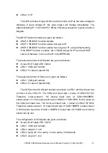
Note that the bypass CAN bus connector is not another CAN channel. It is
designed for connecting to another CAN device conveniently. The structure of the
inside electronic circuit is displayed as figure 2-4.
Figure 2-3 Electronic circuit of CAN bus connector