6
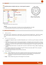
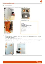
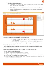
Figure 3 : TMA-3B3 LV radar
connector - Weipu SP1712/P9
8
CABLING
CAUTION: positive security/fail safe relays - contacts given for powered
radar
.
USER’S OUTPUTS
Resistive load: 30 V AC 0.3 A - 60 V DC 0.3 A
REMARKS
•
Make sure the plug is fully inserted in the socket and the cap is firmly tightened on the socket.
•
Please disconnect the radar from the power source before maintenance intervention.
9
INSTALLATION GUIDE
9.1
D
IRECTION DETECTION
The TMA-3B3 measures in both directions, and associates a + sign for the approaching objects and a
–
sign for the receeding
ones. We recommend to install the radar so that the approaching direction is the direction with the largest volume of
cyclists.
9.2
C
HOICE OF THE INSTALLATION LOCATION
•
The TMA-3B3 is designed to measure on dedicated bicycle paths only. It is not able to count the bicycles in mixed traffic
situations.
•
Select a free-flowing section to perform the counting, where targets are not supposed to stop in the sensor beam. Proximity of
intersections is not advised. A bloc of measurements with the same time stamp corresponds to the case where a target
stopped for some time in the "laser" beam. Currently this is not filtered out and generate a "long" target that is then sliced in so
many bicycles.
•
The sensor measures both directions. If the bicycle path is one-direction, install the radar in the way it detects the approaching
direction.
•
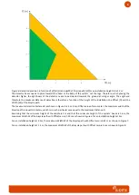
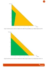
Max. measurement distance of the sensor: about 6 m (angle 45°). This results in a maximum
width “D”
of 4 m, see Figure 4.
•
Max. width of the bicycle path: 4 m, offset included.
•
Avoid obstacles like tree branches or leaves in the beam of the sensor.
9.3
P
HYSICAL INSTALLATION
•
Offset:
distance between the pole and the near edge of the bicycle lane (perpendicular to the bicycles direction)
•
Distance:
distance between the pole and the far edge of the bicycle lane (perpendicular to the bicycles direction).
This distance (D) is equal to the Width (W) of the bicycle path plus the Offset (O)
D = W + O
•
Height:
distance between the ground and the low edge of the radar bracket
LV
(12-16 V DC)
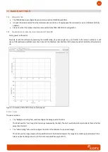
PIN nr
Color
Function
1
RED
Power ~ (AC), + (DC)
2
BLUE
N/A
3
BLACK
Power ~(AC), - (DC GND)
4
BROWN
N/A
5
WHITE /
PURPLE
COM relay 1
6
GREY
NO relay 1
7
YELLOW
NC relay 1
8
GREEN
N/A
9
PINK
/
ORANGE
N/A


