background image

2

SETTING UP THE TRANSCEIVERS

2-16


Connecting the transceiver to the RoIP Gateway

NXDN Conventional mode operation

Set the transceiver channel, volume level, TX output power, and other necessary settings, before 

connecting to the RoIP Gateway.

NOTE:

 Turn OFF both the RoIP Gateway and the transceiver before connecting the cable.

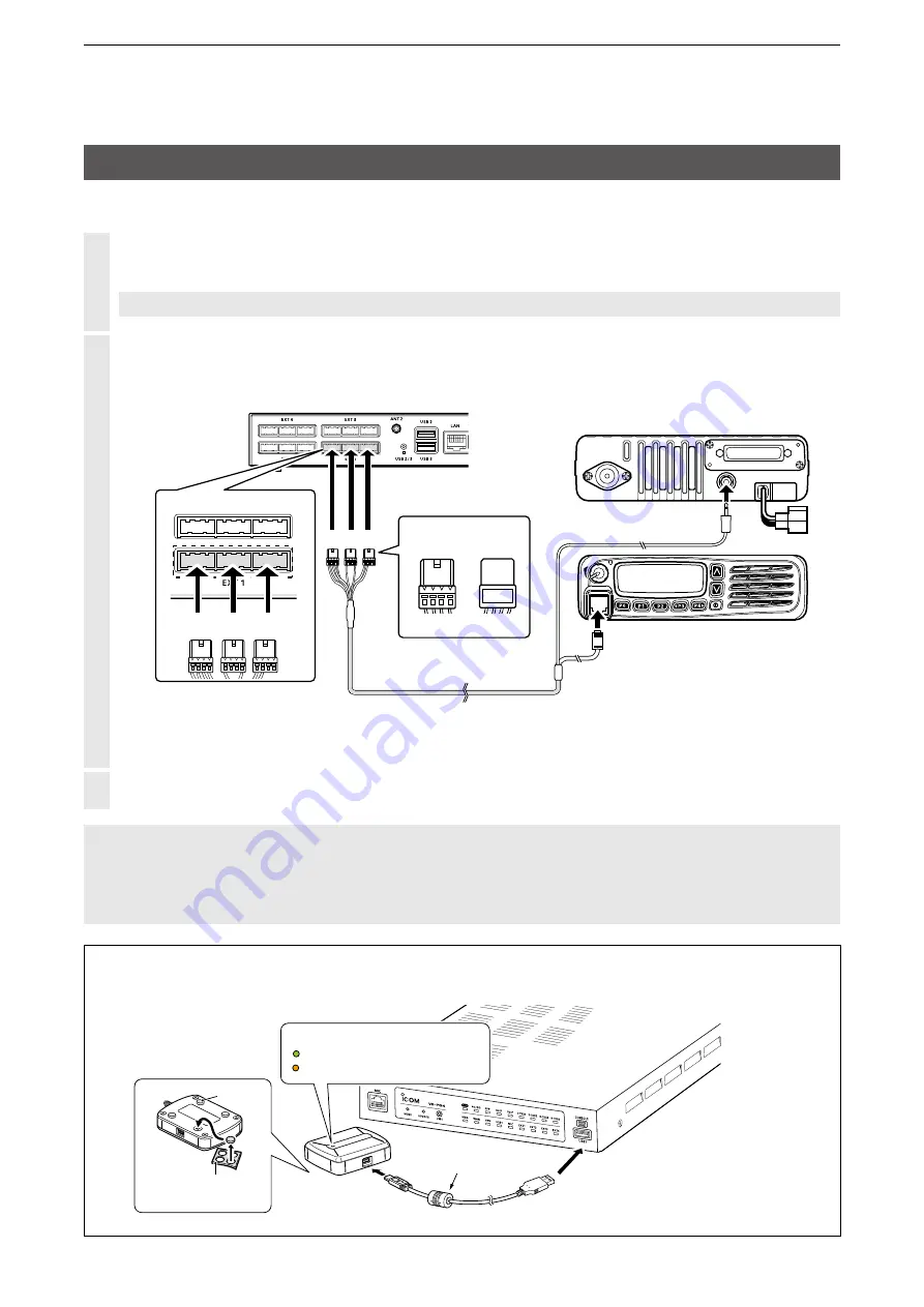
Connect the RoIP Gateway and the transceiver, using the appropriate optional cable.

A1

~

A4

A1

~

A4

B1

~

B4

B1

~

B4

C1

~

C4

C1

~

C4

A1

~

A4

A1

~

A4

B1

~

B4

B1

~

B4

C1

~

C4

C1

~

C4

A1

~

A4

A1

~

A4

B1

~

B4

B1

~

B4

C1

~

C4

C1

~

C4

A1

~

A4

A1

~

A4

B1

~

B4

B1

~

B4

C1

~

C4

C1

~

C4

VE-PG4 (Rear view)

Icom transceiver
(IC-F5060/IC-F6060)

(Rear view)

(Front view)

To the external speaker jack

To the microphone connector

A B C

Be sure to insert the 
connectors top side up

Bottom

Top

A

1

2

3

4

OPC-2275

A1

~

A4

A1

~

A4

B1

~

B4

B1

~

B4

C1

~

C4

C1

~

C4

A

A B C

To [EXT1] (Lower slots)


L

The [EXT1] and [EXT2] ports (lower slots) accept transceivers, by default.

Turn ON the transceiver and the RoIP Gateway.

NOTE:

 •

Turn OFF both the radio and the RoIP Gateway when connecting or disconnecting the transceiver.

 •Keep the radio away from a PC, AC adapter and other electronic equipment. The noise emitted from those 

equipment may interfere with the radio.

 •When operating the radio, do not transmit near the IP telephone.

CT-24

USB cable

(supplied with the CT-24)

Before connecting the cable, 

turn OFF the VE-PG4.

Cushion sheet

(Supplied with the CT-24)

Cushion

leg

Lights green: Power ON

Blinks orange: Communicating

Status Indicator

NOTE: 

4 Internal AMBE+2 vocoders can be assigned to the digital transceivers. If you need an additional 

AMBE+2 vocoder, an optional CT-24 

digital


voice


converter


is required.

Summary of Contents for VE-PG4

Page 1: ...ASIC FUNCTIONS 4 ABOUT THE SETTING SCREEN 5 MAINTENANCE 6 FOR YOUR INFORMATION INTRODUCTION 1 BEFORE USING THE VE PG4 2 SETTING UP THE TRANSCEIVERS 3 WIRELESS LAN TRANSCEIVERS 4 CONFIGURING THE PBX SY...

Page 2: ...red trademarks of Microsoft Corporation in the United States and or other countries AMBE 2 is a trademark and property of Digital Voice Systems Inc All other products or brands are registered trademar...

Page 3: ...munication between transceivers and telephones updating the firmware and backing up or restoring the settings Supports SNMP for network management IP filtering function that restricts access from unkn...

Page 4: ...odec SM 26 desktop microphone to make a call on the VE PG4 2 HM 152 microphone to make a call on the VE PG4 2 HM 241 speaker microphone Future product to directly make a call on the VE PG4 OPC 2389 co...

Page 5: ...ystem default settings L L See the Operating guide for more details on above settings L L The Administrator s Username admin cannot be changed To prevent unauthorized access You must choose a strong p...

Page 6: ...ns for the connections initialization and precautions Installation guide This manual PDF type Instructions for the system requirements the system setup basics maintenance and the specifications It can...

Page 7: ...M MConnecting to the IP transceiver controllers 1 12 M MThe router function 1 12 M MThe VPN function 1 12 M MAudio recorder function 1 12 M MVirtual serial port 1 12 Installation and connections 1 13...

Page 8: ...en In audio data communication with IP transceivers Receive Lights orange In audio data communication with IP transceivers Full duplex Lights red In audio data communication with IP transceivers Trans...

Page 9: ...USB 3 0 Connect a USB flash drive user supplied to save or restore settings or to update the firmware L L You can save the recorded audio on a data storage device through the USB port Only one storage...

Page 10: ...green A USB flash drive is connected Blinks green Accessing the USB flash drive Lights red Failed loading a firmware or backup data from the USB flash drive Not lit Condition other than the above 12 V...

Page 11: ...necessary for the firmware update through the network L L Use a pin to push the button 17 MODE BUTTON Push to initialize the settings See Section 5 for details L L Use a pin to push the button 18 MIC...

Page 12: ...oper device depending on the Line Type setting Router Settings WAN Connection Type See the Operating guide for details Used as a LAN port default Connect a network device such as a Switch or Router mo...

Page 13: ...ecting it to the VE PG4 L L A USB flash drive such as one with biometric authentication or one with password protection is not supported L L Some USB devices may not be usable with the VE PG4 L L The...

Page 14: ...ption Side and bottom panels 1 2 1Security slot Attach a security wire user supplied Refer to the instruction manual that comes with the security wire for details 2SIM card slot Install the SIM card A...

Page 15: ...VoIP telephone Icom transceiver SU Icom repeater SIP server VE PG4 P0 P1 P2 P3 P4 Icom transceiver SU Icom transceiver Icom transceiver EXT1 EXT1 EXT2 VE PG4 VE PG4 Icom transceiver SU IP Network Comm...

Page 16: ...VE PG4 L L You have to connect an optional microphone to the IP100H to make Full Duplex communications You can communicate in the Simplex mode with no external microphone is connected All Call and Gro...

Page 17: ...Multiplex Talkgroup a IP100H can make a Talkgroup Call between the linked Talkgroups Transceiver Controller Common Settings ID List Destination Settings Destination Settings Destination Settings Talkg...

Page 18: ...host computer to send and receive data across shared or public networks like the Internet as if it were a private network L L Configure the VPN connection using the IPsec Refer to the advanced manual...

Page 19: ...ng the magnet legs You can the supplied 4 magnets on the bottom panel and tighten the supplied screws to fix the magnet legs L L Never use other than the supplied screws Installation and connections S...

Page 20: ...nas for the maximum performance L L Adjust the angle or change the antenna location using a base mount for better performance Antenna 2 Supplied Antenna 2 Supplied Tighten clockwise Tighten clockwise...

Page 21: ...ter options 3 Right click Ethernet and then click Properties in the displayed menu list q Right click w Click 4 If the User Account Control message is displayed click Yes to continue 5 In the Ethernet...

Page 22: ...s r Check the LAN cable connection if no indicator lights w q Lights Connected Blinks Communicating q green 1000BASE T w orange 10BASE T 100BASE TX q q Connect cables Connect cables w e The PWR indica...

Page 23: ...on screen is displayed 4 Enter admin fixed username and admin default password in their respective input fields in the Login Authentication window and then click OK q Enter w Click The VE PG4 Setting...

Page 24: ...etting screen description Refer to the Operating guide for each setting item details 1 2 3 1Menu list Displays the list on a menu line When you click each menu a list of the submenu drops down so you...

Page 25: ...e Network and Host For example in the VE PG4 s IP address 192 168 0 1 Class C the digits 192 168 0 are the network digits and the 1 at the end is the host digit Network devices with the same network n...

Page 26: ...RoIP Gateway 2 8 M MConnecting the transceiver to the RoIP Gateway 2 10 M MMaking a call 2 10 NXDN Conventional mode operation 2 11 M MSetting up the UC FR5000 2 11 M MConnecting to a digital radio th...

Page 27: ...L Configure the functions depending on your transceiver system configuration 4 Connecting the transceivers to the VE PG4 pp 2 6 2 10 2 16 Connect the transceivers to the ports using the optional cable...

Page 28: ...SU Icom Transceiver IC F5060 Icom transceiver IC F5060 EXT1 EXT1 VE PG4 VE PG4 IP Network Area A Area B 192 168 0 2 192 168 0 1 A1 B1 Registering a transceiver to the RoIP Gateway 1 Open the EXT I O...

Page 29: ...lick q Confirm The confirmation dialogs are displayed Click OK twice to apply them L When the bridge connection is set the Connection Port setting is deleted from the Destination Settings Destination...

Page 30: ...ers 2 5 Multicast mode operation Registering a transceiver to the RoIP Gateway 4 In Bridge Connection Entry List For Custom Bridge Connection click Activate Confirm the Connection Status has changed t...

Page 31: ...B4 B1 B4 C1 C4 C1 C4 VE PG4 Rear view Icom transceiver IC F5060 IC F6060 Rear view Front view To the external speaker jack To the microphone connector A B C Be sure to insert the connectors top side u...

Page 32: ...m transceiver SU Icom Transceiver IC F5060 Icom transceiver IC F5060 EXT1 EXT1 VE PG4 VE PG4 IP Network Area A Area B 192 168 0 2 192 168 0 1 A1 B1 In Area A 1 While holding down PTT speak at your nor...

Page 33: ...Icom transceiver IC F5060 EXT1 EXT1 VE PG4 VE PG4 IP Network Area A Area B 192 168 0 2 192 168 0 1 A1 B1 Registering the transceiver to the RoIP Gateway 1 Open the EXT I O EXT screen Connection Port...

Page 34: ...w Enter e Click q Confirm The confirmation dialogs are displayed Click OK twice to apply them L When the bridge connection is set the Connection Port setting is deleted from the Destination Settings...

Page 35: ...nection click Activate Confirm the Connection Status is changed to Active q Click w Confirm Connecting the transceiver to the RoIP Gateway Refer to Connecting the transceiver to the RoIP Gateway in Op...

Page 36: ...DT Icom Transceiver Example IC F1100DT Group ID 0006 Group ID 0007 EXT1 ID 0001 ID 0301 ID 0002 ID 0003 ID 0004 SWITCH Repeater B Transceiver A IC FR5000 192 168 0 3 Repeater C IC FR5000 192 168 0 4 I...

Page 37: ...such as the IP address Port Number and Connection Key Code Enter 4 Click Apply 5 In Digital Transceiver Connection click Connect to connect to the Repeater B Connecting is displayed when the RoIP Gate...

Page 38: ...Type Individual Destination ID 0003 Connection Port Digital Transceiver2 D TRX2 Transceiver C2 Destination Settings Destination Settings Destination Settings Call Type Individual Destination ID 0004 C...

Page 39: ...itional Controller IP Transceiver Controller Connection Port and then click Apply q Enter w Click 3 Add the transceiver B2 C1 C2 as the same way 4 In Destination Settings enter the setting for the Gro...

Page 40: ...onventional mode operation Setting for the transceivers Continued on the next page 6 Confirm the entries in List of Destination Setting Entries Group Call and List of Destination Setting Entries Indiv...

Page 41: ...onnectors top side up Bottom Top A 1 2 3 4 OPC 2275 A1 A4 A1 A4 B1 B4 B1 B4 C1 C4 C1 C4 A A B C To EXT1 Lower slots L L The EXT1 and EXT2 ports lower slots accept transceivers by default 3 Turn ON the...

Page 42: ...e destination ID of the A1 A2 example 0301 2 Push PTT and speak at your normal voice level 3 Release PTT to receive With the transceiver A1 or A2 4 Push PTT to answer 5 Release PTT to receive Making a...

Page 43: ...ion IP Network IP Network 4G 3G 4G 3G IP transceiver controller Cloud server ID 0011 Group ID 0013 IP transceiver 1 ID 0012 ID 0008 ID 0009 IP transceiver 2 ID 0301 Group ID 0010 VE PG4 192 168 0 1 Ic...

Page 44: ...e Group 0013 Name Call Type Destination ID and Connection Port and then click Apply Check when you want to call to transceiver Group 0010 from the IP transceiver 1 or 2 w Select q Enter e Click 5 Conf...

Page 45: ...0002 P0 P1 P2 P3 P4 B2 B1 B 1 Open the Microphone MIC screen Connection Port Settings Microphone MIC 2 In Bridge Communication enter the call type destination prefix ID if required and destination ID...

Page 46: ...Destination Settings add a check mark to Microphone MIC in IP Transceiver Controller Connection Port to the setting of that you want to call using the microphone and then click Apply w Click q Select...

Page 47: ...digital transceivers Communication through a bridge connection L L The recording stops after detecting a mute for the set period of time Default 5 seconds L L A data transmission while recording is r...

Page 48: ...ss_group partner s Group ID 0410_101234_group100 wav Group call from to Group100 Individual call mmdd_hhmmss_uid partner s Unit ID 0410_101234_uid10 wav Individual call from to Unit ID 10 Telephone ca...

Page 49: ...transceiver system 3 4 M MConnecting to wireless LAN transceivers 3 4 M MRegistering the wireless LAN transceivers 3 5 M MChecking the IP100H settings 3 6 M MThe Transceiver Settings 3 7 M MThe Group...

Page 50: ...registered to the RoIP Gateway set the wireless LAN settings antenna settings internal or external provisioning server settings RoIP Gateway for all the IP100Hs L L The CS IP100H cloning software can...

Page 51: ...ade with the RoIP Gateway you can register the telephone number of the IP phone Message screen Enter up to 10 messages that the IP100H will send L L Up to 32 characters can be entered for each message...

Page 52: ...wireless access point to the RoIP Gateway network In this manual it is assumed that the IP address of PCs using IP100H or IP100FS is automatically obtained from the DHCP server in the same network as...

Page 53: ...el Name and Unit ID 4 digit and then click Add The Profile ID that is entered on the Profile screen q Enter w Click L L Click OK if a confirmation message is displayed 3 In Transceiver Setting Entry L...

Page 54: ...service area Displayed when your communication terminal is not registered or when not connected to a RoIP Gateway Call mode icon Displays the current call mode The icon blinks when a call or a messag...

Page 55: ...2 In Transceiver Settings select the Unit ID that you want to set up and then enter the required settings To call to an IP telephone enable Clear Down during Telephone Call or assign Clear Down to the...

Page 56: ...reen to make a Group Call L L After completing the settings on this screen restart the IP100H to apply them 1 Open the Destination Settings screen Destination Settings Destination Settings 2 In Destin...

Page 57: ...le to the FUNC key or the ID LIST key See the next page L L After completing the setting on this screen restart the IP100H to apply them 1 Open the Destination Settings screen Destination Settings Des...

Page 58: ...s selected group L L When OFF is selected in step 2 the Talkgroup is released Using the key Usable only when the Talkgroup Call function is assigned to the key 1 Push several times to select Group or...

Page 59: ...restart the IP100H to apply them 1 Open the ID List screen Transceiver Controller Common Settings ID List 2 In ID List Common Settings select an ID list common setting number Example 1 that you want...

Page 60: ...er Settings Transceiver Settings Transceiver Settings L L After completing the settings on this screen restart the IP100H to apply them 1 Open the Messages screen Transceiver Controller Common Setting...

Page 61: ...ransceiver Settings L L After completing the settings on this screen restart the IP100H to apply them 1 Open the Status screen Transceiver Controller Common Settings Status 2 Enter status message of u...

Page 62: ...1 Open the Profile screen Transceiver Controller Common Settings Profile 2 In No select a setting group number that you want to use L L The group number is one that is entered on the Transceiver Regis...

Page 63: ...ceivers 4 9 Setting up the KX series SIP phones 4 10 M MSetting up overview 4 10 M MAssigning a static IP address to the KX UT series phones 4 11 M MAssigning a static IP address to the KX HDV series...

Page 64: ...elephone ring tones for incoming internal and external calls extension priority assignment for the inbound calls and so on p 4 7 PBX Extension Telephone Phonebook for KX series telephones If desired e...

Page 65: ...X series SIP phones by Panasonic are available As of April 2019 L L Each SIP phone must be assigned a unique extension number VE PG4 IP100H Example AP 95M Wireless LAN access point IP100FS Remote comm...

Page 66: ...ered extensions in the List of Extension Entries Confirm PBX Extension The assignable numbers to the extensions Assign a 2 7 digit number Avoid the numbers for emergency calls in your local area Do no...

Page 67: ...reen of the VE PG4 setting screen PBX Special Number 2 Enter the Special Numbers and then click Apply Leave these settings as default unless there is a particular reason not to Enter up to a 3 digit 0...

Page 68: ...ble buttons Example KX UT series 1 Open the Telephone KX UT Series screen PBX Extension Telephone KX UT Series 2 In the Select Group Setting select a group that you want to edit and then click Edit q...

Page 69: ...Apply q Enter w Click 3 Confirm the entry in List of Extension Entries Confirm Example Calling the wireless LAN transceiver 0101 from the SIP phone extension 31 VE PG4 IP100H Example AP 95M Wireless...

Page 70: ...phone to the Destination Settings 1 Open the Destination Settings screen Destination Settings Destination Settings 2 In the Destination Settings Set Call Type to Telephone enter Name and enter the SIP...

Page 71: ...through the EXT port 1 Open the Callee ID to Phone Number screen PBX Transceiver Call Settings Callee ID to Phone Number 2 In Callee ID to Phone Number enter the following items and then click Add De...

Page 72: ...oning maintenance TFTP server p 4 15 Confirm the IP address assigned by the DHCP server SIP PHONE The internal DHCP server automatically provides the required TFTP server information to the SIP phones...

Page 73: ...the display and cursor to move in the menu and push OK or Enter to apply 1Turn ON the SIP phone and then push Setting or Setup 2Open the static IP Address setting screen Setup Network Settings Networ...

Page 74: ...eys below the display and cursor to move in the menu and push OK or Enter to apply 1Turn ON the SIP phone and then push Menu 2Open the static IP Address setting screen Menu System Settings Network Set...

Page 75: ...matically set 2 Confirm the assigned IP address of the SIP phone L L Use the software keys below the display and cursor to move in the menu and push OK or Enter to apply 1Push Setting or Setup 2Open t...

Page 76: ...2 Confirm the assigned IP address of the SIP phone L L Use the software keys below the display and cursor to move in the menu and push OK or Enter to apply 1Push Setting or Setup 2Open the IP Address...

Page 77: ...ce on the left side of the screen 6 In Standard File URL enter tftp your VE PG4 s IP address MODEL _ MAC cfg and then click Save Example when the IP address is 192 168 0 1 tftp 192 168 0 1 MODEL _ MAC...

Page 78: ...CE after the invited extension has answered FLASH RECALL R Disconnects the current call and makes another call without hanging up While transferring a call push this key and then TRANSFER to cancel th...

Page 79: ...all Forward Always Call Fwd No Answer Dial the Special Number for Call Forward No Answer Call Fwd Busy Dial the Special Number for Call Forward Busy Headset Valid on the KX UT123N when a headset is co...

Page 80: ...Touch button if the special number for Call Pickup is assigned Holding or transferring a call Holding a call 1 Push HOLD to hold the call 2 Push the DN key that is slowly blinking in green to retrieve...

Page 81: ...ered REDIAL Redials the last dialed number MUTE AUTO ANS MUTE Mutes or unmutes during a conversation The mute icon blinks on the screen while in the muted mode AUTO ANS Needs to be set in advance Auto...

Page 82: ...nal Call Status Call Fwd Always Push the Special Number for Call Forward Always Call Fwd No Answer Push the Special Number for Call Forward No Answer Call Fwd Busy Push the Special Number for Call For...

Page 83: ...he One Touch button if the special number for Call Pickup is assigned Holding or transferring a call Holding a call 1 Push HOLD to hold the call 2 Push the DN key that is slowly blinking in green to r...

Page 84: ...update 5 7 M MOnline update 5 8 M MOnline update with the UPDATE button 5 9 Automatic Restoring from a USB flash drive 5 10 M MUsing a USB flash drive 5 10 M MUsable USB flash drive specifications 5...

Page 85: ...ttings are lost or damaged 1 Open the Settings Backup Restore screen Management Settings Backup Restore 2 In Settings Backup click Backup The file confirmation screen is displayed No display of the fa...

Page 86: ...layed Click 3 Select the setting file format sav and then click Open The location of the setting file will be entered into the Load Settings File 4 Click Restore and then click OK on the confirmation...

Page 87: ...orange 3 Release the MODE button The PWR indicator lights green when the RoIP Gateway has completed resetting Indicators on the front panel Indicators on the front panel PWR lights green PWR lights gr...

Page 88: ...n dialog is displayed 3 Click OK on the confirmation dialog Click The VE PG4 restarts to restore the settings It may take several minutes to completely reboots CAUTION DO NOT turn OFF both the VE PG4...

Page 89: ...USB flash drive Manually update the firmware from the USB flash drive p 5 15 TOP About the firmware The firmware is a fundamental program for the RoIP Gateway and internally saved on the flash memory...

Page 90: ...ing File item q Click w Click Select the firmware file extension dat 3 After the update is complete click Back Returns to the setting screen If the setting screen is not displayed the update may not b...

Page 91: ...y settings for a backup 1 Open the Firmware Update screen Management Firmware Update 2 In Online Update click Check to check if there is an available firmware update L If there is no update No Firmwar...

Page 92: ...utomatically updates the firmware through Hold down with a pin Release All indicators light orange PWR lights green after rebooted PWR lights green MSG lights green PWR lights green MSG blinks green 1...

Page 93: ...the firmware update is completed check the firmware version on the setting screen to verify that the update was correctly done NOTE for updating the settings or the firmware The firmware or the setti...

Page 94: ...les When restoring the setting data from a USB flash drive to the RoIP Gateway its original settings are automatically saved as bakdata sav onto the USB flash drive as a backup The latest 11 backup fi...

Page 95: ...t bakdata_2 sav savedata sav 0090C7000022 bakdata sav bakdata_1 sav firmware dat bakdata_2 sav savedata sav 0090C7000033 bakdata sav bakdata_1 sav firmware dat bakdata_2 sav savedata sav USB drive E T...

Page 96: ...setting screen of the RoIP Gateway 3 Open the Settings Backup Restore screen Management Settings Backup Restore 4 In Settings Backup click Backup Click The dialog is displayed 5 Click of Save select...

Page 97: ...1 indicator turns OFF and then remove the USB flash drive from the VE PG4 L L The automatically saved VE PG4 settings data is located as the bakdata sav on the USB flash drive USB1 port Push USB1 e Re...

Page 98: ...port example USB1 port of the VE PG4 The USB1 indicator lights green when the USB flash drive is successfully mounted 5 Push the USB1 button The VE PG4 reboots to update the firmware 6 Confirm the PWR...

Page 99: ...writes the setting data or the firmware from to only the USB flash drive that has a matching authentication key 1 Insert the USB flash drive into the USB port example USB1 port of the VE PG4 The USB1...

Page 100: ...authentication key already exists you are asked if you want to overwrite it or not Click Close Click 6 Confirm the PWR indicator lights green and hold down USB1 button until the USB1 indicator turns O...

Page 101: ...5 The setting screen menu list 6 6 The feature functions 6 12 About the external audio device 6 13 M MConnecting to an external audio device 6 13 Using the Virtual serial port 6 14 M MPreparation on...

Page 102: ...Disable the web browser s proxy server setting Click Tools in the web browser menu and then click Internet option Click the Connections tab then click LAN settings and then confirm there is no check...

Page 103: ...in the Always on connection mode Set the Always on connection mode to disable The output audio signal from the OUT port does not fade in or fade out The EXT 1 4 port setting is incorrect Set the EXT I...

Page 104: ...ment Administrator Administrator Password 2 If Telnet SSH is successfully connected to the RoIP Gateway VE PG4 is displayed Saving the setting After making changes enter save and then push the Enter k...

Page 105: ...om network devices is required Download the USB driver and the manual from the Icom web site and install it according to the manual http www icom co jp world support After installing the USB driver se...

Page 106: ...uting Routing Table Static Routing List of Static Routing Entries Policy Routing Source Address Routing List of Source Address Routing Entries Router Settings WAN Connection Status Connection Type NAT...

Page 107: ...ireless LAN List of Wireless LAN Entries ID List ID List Common Settings ID List Advanced Settings Save or Write the ID List Setting ID List ID List Entries Messages Message Group Message Group Detail...

Page 108: ...Destination Setting Entries Telephone Destination Batch Setting Expert Settings Emergency Notification Emergency Notification Abnormal Condition Monitoring LAN Port Link down PING Test SIP Server Reg...

Page 109: ...ttern Ringtone Pattern Assignment Telephone Common Settings Telephone Individual Settings KX UT Series Button Assignment Telephone KX HDV Series Telephone Maintenance Telephone Group Dial Tone Busy To...

Page 110: ...Settings List of Outbound Call Restriction Rule Settings Outside Line Regulation Outside Line Regulation External Call Limiting Overall Limitation Limitation for each Outside Line IP Authenticated Ex...

Page 111: ...6 For your information 6 11 The setting screen menu list Menu Setting screen Setting item Firmware Update Firmware Status Online Update Automatic Update Manual Update...

Page 112: ...bound number reformatting Outbound call restriction External line controls Router PPPoE connection DHCP client Static IP connection IP masquerade Static IP masquerade DMZ DHCP server Static DHCP serve...

Page 113: ...h pin assignments as follows See page 6 20 for details on the port L L The A2 A4 B4 terminals are GND L L The B1 B4 terminals can be configured on the setting screen B Connectors Top panel A1 A2 A3 A4...

Page 114: ...ndows 7 32 64 bit Service Pack1 or later Optional cable OPC 2389 Connect the VE PG4 and the serial device using the modified RS 232C cable as shown below B C Connector Top panel C1 Wiring example When...

Page 115: ...r Connection 1 Open the EXT I O EXT screen Connection Port Settings EXT I O EXT 2 Select EXT I O3 EXT3 Select 3 Set EXT I O to EXT I O 3 EXT3 Enter the serial communication settings in the EXT Output...

Page 116: ...pens L L Click Yes in the User account Control dialog if displayed 4 Click Add Click L L You can add up to 64 virtual serial ports L L If a security warning dialog is displayed or the application asks...

Page 117: ...s of the VE PG4 and the TCP port number and then click OK Uncheck when you set the Data Mode p 6 15 to Auto q Select w Enter These settings are typically set by the applications that uses the serial c...

Page 118: ...Double click VirtualSerialPort exe The Virtual Serial Port application opens L L Click Yes in the User account Control dialog if displayed 4 Select a COM port that you want to delete Example COM7 and...

Page 119: ...D TRX1 4 MSG WAN VPN USB1 MIC EXT1 4 USB2 3 Buttons MODE UPDATE USB1 USB2 3 USB ports USB A type USB 3 0 3 ports CONSOLE port USB mini B type USB 2 0 1 1 Communication interfaces Network ports WAN LA...

Page 120: ...erminal Adjust the output gain according to the audio amplifier that is used The connected audio equipment may be damaged if the gain is inappropriately set The length of the cable that connects the a...

Page 121: ...VE PG4 C3 Serial communication RTS From the VE PG4 C4 Serial communication CTS To the VE PG4 L L You can change the configuration of ports B1 to B4 on the VE PG4 setting screen B1 B4 terminal General...

Page 122: ...1 1 32 Kamiminami Hirano ku Osaka 547 0003 Japan A7487 3EX 2019 Icom Inc Apr 2019...

Reviews: