Jumper wire
J5 pin 21
J5
16
INSTRUCTIONS
TRUNKING UNIT
UT-111
Thank you for purchasing the UT-111 TRUNKING
UNIT.
Please read these instructions before installing and
using this product.
D
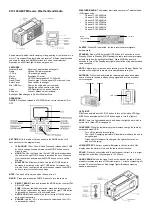
IC-F3 and IC-F4 series instructions
q
Remove the battery pack and volume knob and un-
screw the antenna connector screw.
w
Unscrew the 2 screws, then remove the front panel
as shown below.
e
Remove the shielding plate and 7 screws to show
the bottom view of the MAIN unit.
r
Connect 2 points of the MAIN unit with a jumper
wire as shown at right.
t
When using the UT-111 with IC-F3/S, connect JP2
by soldering as shown below.
y
Plug the UT-111 to J5 on the MAIN unit.
u
Reassemble the transceiver.
D
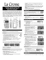
UT-111 modification (IC-F3/S)
When using the UT-111 with IC-F3/S, connect JP2 by
soldering as shown below.
IC-F3/F4 SERIES PC BOARD MODIFICATION
U2
JP1
JP2
U3
MODEL
IC-F3/S
Jumper
Open
IC-F4/S
JP2 JUMPER
D
MAIN unit modification
Connect 2 points with a jumper wire as shown below.
• IC-F3/S
• IC-F4/S
This modification is not required when the trans-
ceiver’s serial number is over 60000.
B4929E
Jumper wire
J5 pin 21
J5
16
- 1 -