


2
SETTING UP THE IP1000C SYSTEM
2-14
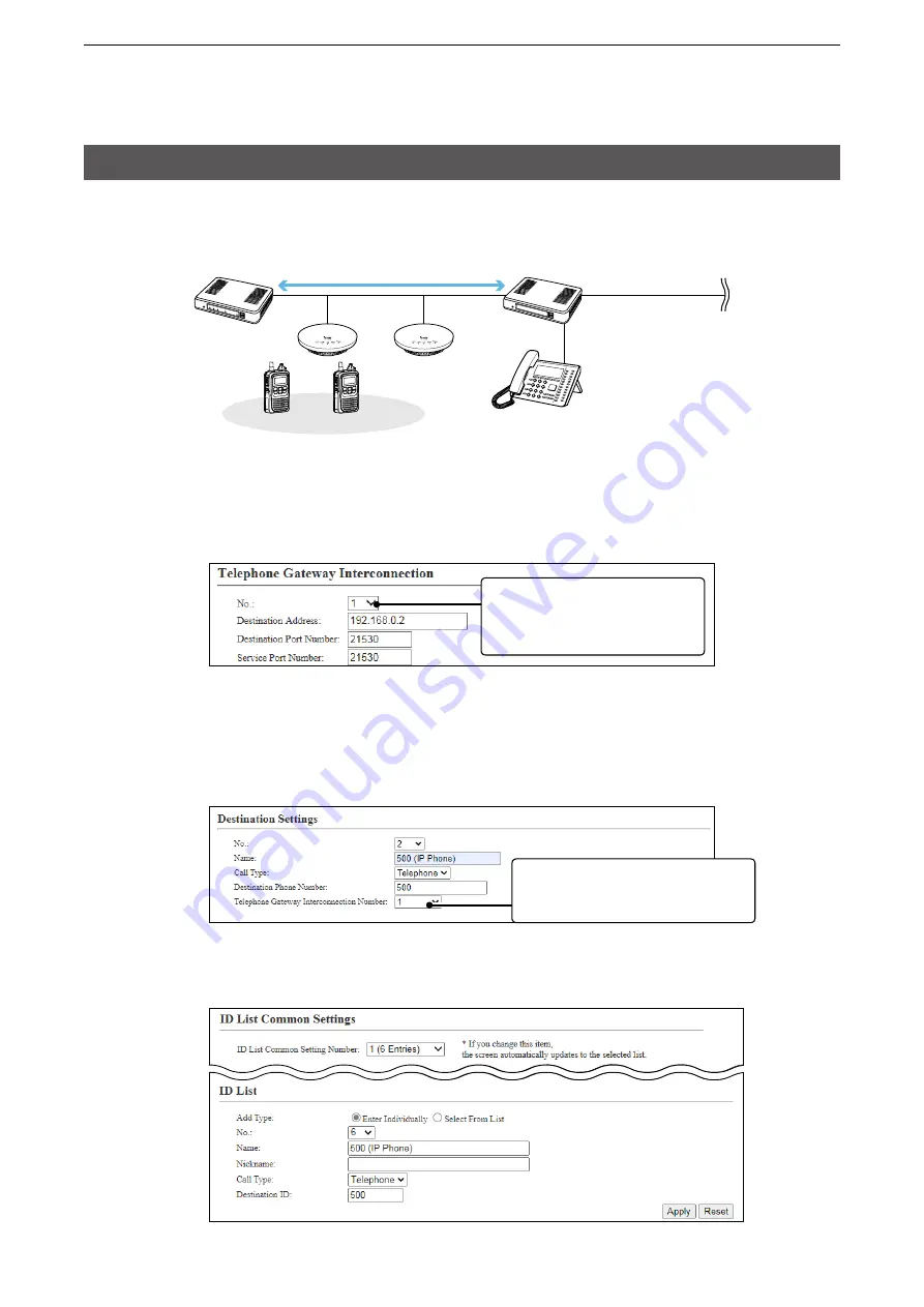
About the IP1000C settings
1. Enter the IP address of the VE-PG3 in the [Telephone Gateway Interconnection] field. (Example:
192.168.0.2)
[RoIP Server Settings] (menu) > [Telephone Gateway Interconnection] (screen) >
[Telephone Gateway Interconnection] (field)
192.168.0.2
192.168.0.1
Sales2
00002
Sales1
00001
Seles group1
00011
Extension number 2001
Extension number 500
IP1000C
VE-PG3
IP100H
Wireless
access point
Bridge connection
IP phone
(RoIP Gateway)
This number is the same as the “No.”
item in the [Telephone Gateway
Interconnection Number] field.
3. Bridge connection and Caller settings
When making a bridge connection with a VE-PG3*, the IP1000C system can communicate with the transceivers.
* A VE-PG3 with a firmware version 1.13 or less cannot communicate with the IP1000C system.
Before connecting the VE-PG3, check the firmware version on the VE-PG3’s setting screen.
This number is the same
as the “Telephone Gateway
Interconnection Number” item in
the [Destination Settings] field.
2. After setting the “Call Type” item to “Telephone,” select the “Telephone Gateway Interconnection Number”
item and then enter a telephone number in the “Destination Phone Number” item.
[Destination Settings] (menu) > [Destination Settings] (screen) > [Destination Settings] (field)
•
Select the bridge number as same as the number that is selected the [Telephone Gateway Interconnection] field.
(Example: 1)
•Enter the VE-PG3’s extension number. (Example: 500)
3. After setting the “Call Type” item to “Telephone,” enter the “Destination Phone Number” item.
[Common Settings] (menu) > [ID List] (screen) > [ID List] (field)
•Enter the VE-PG3’s extension number. (Example: 500)