background image

17

5

BASIC OPERATION

New2001

1
2
3
4
5
6
7
8
9
10
11
12
13
14
15
16

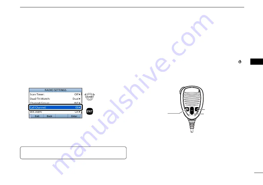
By default, a Call channel is set in each Channel Group.

You can set the Call channel with your most often-used 

channel for quick recall.

1.   Push  [MENU].


The “MENU” screen is displayed.

2.   Rotate [CH/ENT] to select “Radio Settings,” then push 

[ENT].

3.   Rotate [CH/ENT] to select “Call Channel,” then push 

[ENT].


+

Push

Rotate


 The “CALL CHANNEL” screen is displayed.

4.   Rotate [CH/ENT] to select a channel to be set as the 

Call channel, then push [ENT].

5.   Push [MENU] to return to the Main screen.


Setting the Call channel

TIP:

 To confirm that your setting is correctly set, hold 

down [16/C] for 1 second. (p. 14)


 Microphone Lock function

The Microphone Lock function electrically locks [

], [

], 

[16/C] and [H/L] on the supplied microphone. 

This prevents accidental channel changes or function access.

 While holding down [H/L] on the microphone, hold down [ ] 

for 1 second to turn ON the transceiver.


 The Microphone Lock function is turned ON or OFF.

[

], [

]

[16/C]

[H/L]

Summary of Contents for IC-M605E

Page 1: ...INSTRUCTION MANUAL VHF MARINE TRANSCEIVERS iM605EURO iM605...

Page 2: ...shock may occur CAUTION Equipment damage may occur NOTE If disregarded inconvenience only No risk of personal injury fire or electric shock CLEAN THE FRONT PANEL THOROUGHLY IN A BOWL OF FRESH WATER af...

Page 3: ...d above ii INSTALLATION NOTE Installation The installation of this equipment should be made in such a manner as to respect the EC recommended electromagnetic field exposure limits 1999 519 EC The maxi...

Page 4: ...antenna when persons are within the MPE radius of the antenna unless such persons such as driver or radio operator are shielded from antenna field by a grounded metallic barrier The MPE Radius is the...

Page 5: ...rouvent l int rieur du rayon d exposition maximale admissible de cette antenne moins que ces personnes comme le conducteur ou l op rateur radio ne soient prot g es du champ de l antenne par un cran m...

Page 6: ...communications Operation of this equipment in a residential area is likely to cause harmful interference in which case the user will be required to correct the interference at his own expense NOTE A W...

Page 7: ...KEEP the transceiver and microphone at least 1 meter away from the vessel s magnetic navigation compass CAUTION DO NOT place or leave the transceiver in areas with temperatures below 20 C 60 C 4 F 14...

Page 8: ...direct telles le tableau de bord NE PAS nettoyer l appareil avec des solvants agressifs tels que benz ne ou alcool susceptibles d endommager les surfaces expos es du boitier En cas de d p t de poussi...

Page 9: ...DEFINITIONS i IN CASE OF EMERGENCY ii INSTALLATION NOTE ii RADIO OPERATOR WARNING iii AVERTISSEMENT POUR LES OP RATEURS RADIO iv FCC INFORMATION v NOTE v PRECAUTIONS vi PR CAUTIONS vii ACTION ICON DE...

Page 10: ...sing the Intercom 67 Using the RX Hailer 68 Using the Hailer 68 Using the Horn 69 Using the Voice Scrambler 71 Using the Voice Recorder 72 10 AIS RECEIVER 73 83 About AIS 73 AIS Classes 73 Function di...

Page 11: ...your craft s identification for radio purposes 2 OPERATOR S LICENSE A Restricted Radiotelephone Operator Permit is the license most often held by small vessel radio operators when a radio is not requ...

Page 12: ...U KEY MENU Speaker Function display w ENTER KEY ENT e LEFT AND RIGHT KEYS r UP AND DOWN KEYS t KEYPAD y POWER KEY u CHANNEL 16 CALL CHANNEL KEY 16 C i VOLUME SQUELCH DIAL VOL SQL o CLEAR KEY CLR 0 CHA...

Page 13: ...ters or symbols For channel number entry see page 14 For channel name entry see page 20 y POWER KEY Hold down for 1 second to turn the transceiver ON or OFF u CHANNEL 16 CALL CHANNEL KEY 16 C z z Push...

Page 14: ...p 22 Except for the Dutch version Push to start or stop a Normal or Priority scan Dualwatch Tri watch DW TW p 24 Except for the Dutch version Push to start or stop the Dualwatch or Tri watch AIS p 74...

Page 15: ...Name p 20 Push to display the CHANNEL NAME screen Backlight p 5 Push to open the Backlight Settings window DSC Log p 58 Push to display the RECEIVED CALL LOG screen Software Key function The transcei...

Page 16: ...down for 1 second to select the Call channel The CALL icon is displayed q PTT SWITCH PTT w UP DOWN KEYS Y Z e TRANSMIT POWER KEY H L Microphone r CHANNEL 16 CALL CHANNEL KEY 16 C Information area Sof...

Page 17: ...r Description Displayed when a Favorite channel is selected CALL Displayed when the Call channel is selected by holding down 16 C for 1 second DUP Displayed when a Duplex channel is selected Displayed...

Page 18: ...ks when invalid GPS data is being received Displayed when there are unread DSC messages Blinks when a DSC message is received Displayed when the CH Auto Switch in DSC Settings is set to an option exce...

Page 19: ...ort beeps sound Push ENT to Register Your MMSI is displayed 2 Push ENT to enter the MMSI code entry mode Push Push CLR to cancel the entry In that case the transceiver displays Push ENT to Register Yo...

Page 20: ...nly your dealer or distributor can change it If your ATIS ID has already been entered this entry is not necessary 1 Push MENU 2 Select ATIS ID Input then push ENT 3 Enter a 10 digit ATIS code 4 After...

Page 21: ...reen Horn p 69 Manual Horn Hold down Horn to sound a horn Auto Foghorn Select the automatic foghorn pattern Frequency Select the foghorn s audio frequency Intercom 2 p 67 RADIO Displays the transceive...

Page 22: ...tion Input 2 Enter your position Individual ID Enter an Individual ID Group ID Enter a Group ID Auto ACK Select whether or not to automatically transmit an Acknowledgement after receiving each type of...

Page 23: ...1 Push MENU to display the MENU screen 2 Rotate CH ENT to select Radio Settings then push ENT Push Rotate 3 Rotate CH ENT to select Dual Tri Watch then push ENT Push Rotate 4 Rotate CH ENT to select T...

Page 24: ...have a leisure use Call channel for quick recall To set your most used channel see page 17 The default Call channel differs depending on the transceiver version z z Hold down 16 C for 1 second Display...

Page 25: ...version Version Preset Channel Group USA INT CAN DSC ATIS USA UK European Dutch German Chinese 1 Push MENU The MENU screen is displayed 2 Rotate CH ENT to select Radio Settings then push ENT Push Rot...

Page 26: ...ing a Weather channel 1 Push or until CH WX is displayed in the Software Key area 2 Push CH WX Push WX is displayed instead of the Channel Group icon 3 Rotate CH ENT to select a Weather channel Rotate...

Page 27: ...screen is displayed 4 Rotate CH ENT to select a channel to be set as the Call channel then push ENT 5 Push MENU to return to the Main screen Setting the Call channel TIP To confirm that your setting...

Page 28: ...e high power for longer distance communications 1W is displayed when low power is selected Choose low power for short range communications Some channels are restricted to low power 7 Hold down PTT and...

Page 29: ...time operation and the screen items are in black and red 1 Push or until Backlight is displayed in the Software Key area 2 Push Backlight to open the Backlight Settings window Push 3 Push or to select...

Page 30: ...Enter a channel name Push Rotate Entering a Channel name L Informatio L You can enter the following characters by pushing the keypad one or more times KEY ENTRY KEY ENTRY 1 1 6 6 M N O 2 2 A B C 7 7...

Page 31: ...ll by vibrating the speaker 1 Push MENU The MENU screen is displayed 2 Rotate CH ENT to select AquaQuake then push ENT 3 Hold down Aqua Quake until all water is removed from the speaker grill Hold dow...

Page 32: ...et the scan type to Normal or Priority p 88 NORMAL SCAN A Normal scan sequentially scans all Favorite channels However the scan does not check Channel 16 unless it is set as a Favorite channel CH 01 C...

Page 33: ...OFF you can select all channels p 90 D D Clearing 1 Select a Favorite channel to clear 2 Push Favorite to clear the channel as the Favorite channel disappears Example Starting a priority scan Scanning...

Page 34: ...l channel disappears Operation 1 Select Dualwatch or Tri watch in the Menu screen p 89 2 Select a channel p 14 3 Push DW or TW to start Dualwatch or Tri watch During Dualwatch DUAL 16 is displayed Dur...

Page 35: ...1 and 9 A 0 in the first digit is used for a Group ID A 0 in the first two digits is used for any Coast station ID 5 After entering all 9 digits push Finish 6 Enter the ID name L L See page 20 for tex...

Page 36: ...to the Main screen D D Deleting an entered ID 1 Push MENU 2 Select Individual ID or Group ID then push ENT DSC Settings Individual ID DSC Settings Group ID 3 Rotate CH ENT to select the ID to delete 4...

Page 37: ...data is received Manually entered position and time are valid for only 23 5 hours 1 Push MENU 2 Select Position Input then push ENT DSC Settings Position Input 3 Enter your position s latitude To sel...

Page 38: ...screen Push Exit To go back to the previous screen Push Back When position and time data are set Latitude Longitude and UTC time are displayed Latitude 25 32 1234N Longitude 135 23 4321E UTC time 12 0...

Page 39: ...ns When entering the Task mode the following functions are displayed first FUNCTION DESCRIPTION Standby Push to delete the task and returns to the Main screen Resend Push to resend the call The follow...

Page 40: ...ON DESCRIPTION Standby Push to hold the task and returns to the Main screen Delete Push to delete the task and display the Task list Hold Push to hold the task and display the Task list Task List Push...

Page 41: ...und and both the key and display backlighting blink 3 After sending the following screen is displayed Channel 16 is automatically selected 4 When receiving the acknowledgement Alarm sounds The followi...

Page 42: ...Man Overboard L L The transceiver stores this setting for 30 seconds You can skip Step 3 below if your position and time data are valid In that case go to Step 4 Step 3 Entering Position 1 Select Posi...

Page 43: ...urs or until the power is turned OFF Waiting for an acknowledgement The transceiver automatically sends a Distress call every 3 5 to 4 5 minutes until receiving an acknowledgement Call repeat mode or...

Page 44: ...hen the acknowledgement is received Alarm sounds The following screen is displayed 4 Push any Alarm Off 5 Push any Close Call RCVD Window 6 Hold down PTT to announce your situation 7 Push Standby to r...

Page 45: ...re key functions 2 Push Continue to send a Distress Cancel call Push 3 After sending the following screen is displayed 4 Hold down PTT to announce your cancel statement L L Rotate CH ENT to view the c...

Page 46: ...e 4 Push to scroll the software key functions 5 Push ACK Push The call contents screen is displayed L L Rotate CH ENT to view the call contents 6 Push Call to send the Distress Relay acknowledgement P...

Page 47: ...tion enables you to transmit a DSC call to only a specific coast station or to a ship After transmission wait for an acknowledgement from the receiving station You can communicate by voice after recei...

Page 48: ...e channel specified in step 5 is selected A different voice channel is selected if the station you called cannot use the channel 7 After sending the following screen is displayed L L See page 29 or pa...

Page 49: ...ept Push Enters the DSC Task mode 4 Select your action ACK Able Sends an acknowledgment without any changes ACK Unable Sends an acknowledgment but you cannot make a communication ACK New CH Sends an a...

Page 50: ...om the Menu screen MENU Compose Non Distress 2 Select Message Type then push ENT 3 Select All Ships then push ENT 4 Select Category then push ENT 5 Select the option then push ENT Example Safety 6 Sel...

Page 51: ...ENT 4 Select Address then push ENT 5 Select the Group address or Manual Input then push ENT Example GROUP1 When you select Manual Input in step 5 push the keypad to manually enter the Group ID p 26 6...

Page 52: ...ss 2 Select Message Type then push ENT 3 Select the call to send then push ENT 4 Select Address then push ENT 5 Select an Individual address or Manual Input Example STATION1 When you select Manual Inp...

Page 53: ...all contents Change your position data if the displayed data is invalid p 27 5 Push Call to send the acknowledgement When ACK Able is selected in step 5 your position and time data are transmitted 6 P...

Page 54: ...NU Compose Non Distress 2 Select Message Type then push ENT 3 Select Test 4 Select Address then push ENT Push Rotate D D Sending a Polling Reply call For only the USA version Send a Polling Reply call...

Page 55: ...to send the Test call Push 7 After sending the following screen is displayed L L See page 29 or page 30 for details of the Task mode s Software key functions Push Rotate 8 When the acknowledgement is...

Page 56: ...en Test ACK is set to Auto the transceiver automatically sends the acknowledgement p 60 When a Test call is received you can send an acknowledgement 4 Push ACK Push The call contents screen is display...

Page 57: ...hip If the distress call continues even after the coast station sends back an acknowledgement the ship in distress may not receive the acknowledgement Hold Holds the RX call task and returns to the Ma...

Page 58: ...g a Distress acknowledgement 1 When a Distress acknowledgement sent to another ship is received Alarm sounds The following screen is displayed and the backlight blinks blinks 2 Push any Alarm Off 3 Pu...

Page 59: ...stress Relay call is received Alarm sounds The following screen is displayed and the backlight blinks blinks 2 Push any Alarm Off 3 Select the action Ignore Ignores the Call and returns to the Main sc...

Page 60: ...Alarm Off 3 Push any Close Call RCVD Window Enters the DSC Task mode D D Receiving a Distress Relay acknowledgement DSC Task mode pp 29 30 Automatically selects Channel 16 and then you should monitor...

Page 61: ...set to Auto the transceiver automatically sends an acknowledgement Both the TX and RX calls are stored in the Transmitted and Received Call Logs pp 58 59 When you select Accept in step 3 you can send...

Page 62: ...played and the backlight blinks blinks 2 Push any Alarm Off D D Receiving an Individual acknowledgement 3 Push any Close Call RCVD Window Enters the DSC Task mode DSC Task mode pp 29 30 Automatically...

Page 63: ...e voice communication on the channel that is proposed by the called station 1 When an Individual acknowledgement ACK New CH is received Alarm sounds The following screen is displayed and the backlight...

Page 64: ...ollowing screen is displayed and the backlight blinks blinks 2 Push any Alarm Off 3 Select your action Ignore Ignores the Call and returns to the Main screen Displayed only when Single is selected in...

Page 65: ...urns to the Main screen Displayed only when Single is selected in the PROCEDURE menu p 64 Hold Holds the RX call task and returns to the Main screen Pause Pauses the countdown To restart the countdown...

Page 66: ...d Alarm sounds The following screen is displayed and the backlight blinks blinks 2 Push any Alarm Off 3 Select your action NOTE When Test ACK or Polling ACK is set to Auto the transceiver automaticall...

Page 67: ...ush Standby to return to the Main screen Ignore Ignores the Call and returns to the Main screen Displayed only when Single is selected in the PROCEDURE menu p 64 Hold Holds the RX call task and return...

Page 68: ...sage then push ENT Push Rotate 4 Rotate CH ENT to view the contents To view another message push CLR to return to the previous screen Then select the message 5 Push Exit to return to the Main screen T...

Page 69: ...ted Call Log Push Rotate 3 Select the message then push ENT Push Rotate 4 Rotate CH ENT to view the contents To view another message push CLR to return to the previous screen Then select the message 5...

Page 70: ...he Individual ACK item to Auto Unable and receive the Individual call the transceiver automatically sends the acknowledgment including ACK Unable No Reason Given 1 Push MENU 2 Select Auto ACK DSC Sett...

Page 71: ...annel for 10 seconds After that the transceiver automatically switches to the channel that assigned by the received DSC call Ignore after 10 sec 1 After receiving a DSC call the transceiver remains on...

Page 72: ...item then push ENT DSC Settings Alarm Status Safety DSC Settings Alarm Status Routine Example Safety Push Rotate 3 Select the option then push ENT On Alarm sounds Default Off Alarm does not sound 4 Pu...

Page 73: ...evel on Channel 70 The transceiver has 11 squelch levels between 1 loose squelch 10 tight squelch and Open squelch is completely open 1 Push MENU 2 Select CH 70 SQL Level then push ENT 3 DSC Settings...

Page 74: ...ransceiver handles a single task Default Multiple The transceiver can handle up to 7 tasks at same time 4 Push MENU to return to the Main screen D D Self Check Test The Self Check test function sends...

Page 75: ...irm the transceiver is in the normal operating mode Otherwise you cannot make an Individual DSC call using the transponder 2 Push DSC to display the Voice channel selection screen and then push Y Z to...

Page 76: ...FF to stop the alarm and then select the Intership channel specified in step 2 A different Intership channel will be selected if the station you called cannot use the channel To reply push PTT and spe...

Page 77: ...it then push ENT Enters the Intercom mode 4 Hold down Call to sound the intercom beeps The transceiver and the command head or command microphone sound beeps while holding down Call Call is displayed...

Page 78: ...e push RX Hailer The icon disappears Using the Hailer You can talk without leaving the bridge by using the 2 way hailer function Connect an external hailer speaker as described on page 94 You cannot t...

Page 79: ...0 seconds Two 5 second blasts separated by 2 seconds every 120 seconds One 5 second blast followed by two 1 second blasts each separated by 2 seconds every 120 seconds One 5 second blast followed by t...

Page 80: ...rn 3 Select the foghorn pattern then push ENT 4 Rotate CH ENT to adjust the foghorn level D D Using the Automatic foghorn function Continued 5 Push Exit to return to the Main screen The icon is displa...

Page 81: ...ush SCBL to turn the Voice Scrambler ON or OFF The SBL icon is displayed when the voice scrambler is ON D D Setting scrambler codes Set the code to between 1 and 32 in the Menu screen In order to unde...

Page 82: ...recording automatically when the signal is received The icon is displayed while recording Stops recording 3 seconds after the signal disappears Stops recording when the channel is changed The recorde...

Page 83: ...ansmitter AIS SART Man OverBoard MOB and Emergency Position Indicating Radio Beacon AIS EPIRB AIS There are 2 classes of AIS units which are installed on vessels Class A and Class B Under the Safety O...

Page 84: ...S target e YOUR VESSEL ICON Displayed in the center of the screen L L When N UP is displayed the vessel icon automatically points in the direction you are heading in 45 degrees steps L L When COG UP i...

Page 85: ...tter screen 6 minutes and 40 seconds after the vessel was regarded as a Lost target Ask your dealer for details D D Target list screen In the plotter screen push Display to enter the target list scree...

Page 86: ...w q THE NUMBER OF DANGEROUS TARGETS Displays the number of AIS targets which are being detected by the transceiver w DANGER TARGET INFORMATION Displays the following dangerous target information MMSI...

Page 87: ...enna length Length Beam Draught Type of Ship Navigation Status Destination Date Time D D Content lists of Class B vessels DETAIL screens AIS Class MMSI Code Ship Name Country Name Call Sign Vendor ID...

Page 88: ...Antenna length Stern to Antenna length Port side to Antenna length Starboard side to Antenna length Length Beam Position Indicator ON POS ON Position OFF POS OFF Position Type of AtoN D D Content lis...

Page 89: ...e to Antenna length Starboard side to Antenna length Length Beam Draught Type of Ship Navigation Status Destination Date Time D D Content lists of EPIRB AIS targets DETAIL screens Type of AIS Target M...

Page 90: ...exit the AIS combo screen AIS Settings AIS settings can be customized from AIS Settings on the menu screen 1 Push MENU 2 Select AIS SET then push ENT D D North up COG UP Select the display type for th...

Page 91: ...er To prevent this when the anchored vessel s SOG is less than this set value the Slow Warn function assumes that vessel s COG is fixed towards your vessel and an alarm will sound z z Rotate CH ENT or...

Page 92: ...CPA Set between 1 and 60 minutes in 1 minute steps default 20 min D D ID BLOCKING The transceiver blocks AIS transponders that are entered into the ID blocking list Enter your vessel s transponder ID...

Page 93: ...ush MENU 2 Select ID Blocking then push ENT AIS Settings ID Blocking 3 Select the ID to edit then push Edit 4 After editing push Finish to set it Deleting an ID 1 Push MENU 2 Select ID Blocking then p...

Page 94: ...ation item Ref item Ref Key Beep p 85 Speaker p 87 Key Assignment p 85 Noise Cancel p 87 UTC Offset p 86 Power SW from Sub Unit p 88 Inactivity Timer p 86 D D Radio Settings item Ref item Ref Scan Typ...

Page 95: ...N or OFF On Sounds a beep when pushing a key Default Off Does not sound a beep when pushing a key for silent operation D D Key Assignment Configuration Key Assignment Assign functions to Software keys...

Page 96: ...ion Inactivity Timer DSC Related The transceiver automatically returns to the Main screen if no key is pushed for this set period of time Default 15 min This setting is for when the LCD displays a scr...

Page 97: ...ooth reception TX It is effective to turn ON the TX noise cancel function when you operate under a noisy surround area Distress Related Configuration Inactivity Timer Distress Related The transceiver...

Page 98: ...d head Radio Settings D D Scan Type Except for the Dutch version Radio Settings Scan Type Select the Scan type to locate signals Normal Scan Sequentially searches all Favorite channels Default for the...

Page 99: ...Select a channel group suitable for your operating area Selectable channel group and the default setting may differ depending on the transceiver version D D Call Channel Radio Settings Call Channel Y...

Page 100: ...le the Voice recorder p 72 by selecting Off Default Auto Last 120 sec D D FAV Settings Radio Settings FAV Settings Set the Favorite channel settings Set All Channels Sets all channels as Favorite chan...

Page 101: ...sponder D D NMEA 2000 NMEA Settings NMEA 2000 NMEA 2000 is a communication standard used to connect various marine devices and display units in the vessel The transceiver can easily connect to a NMEA...

Page 102: ...col Data Transfer 060416 ISO Transport Protocol Connection Management 065240 ISO Commanded Address 059392 ISO Acknowledgement 059904 ISO Request 060928 ISO Address Claim 126208 NMEA Request Command Gr...

Page 103: ...over ground Rapid Update 129029 GNSS Global Navigation Satellite System Position Data 129799 Radio Frequency Mode Power 129808 DSC Call Information 129038 AIS Class A Position Report 129039 AIS Class...

Page 104: ...e front panel e EXTERNAL SPEAKER CONNECTOR Connects the optional SP 37 horn speaker External speaker External speaker NC NC Hailer Speaker Hailer Speaker Transceiver s rear panel view r GROUND TERMINA...

Page 105: ...receive signals from satellites o ANTENNA CONNECTOR Connects to a marine VHF antenna with a PL 259 connector CAUTION Transmitting without an antenna may damage the transceiver D D NMEA 0183 In Out li...

Page 106: ...Benzine or alcohol as they will damage transceiver s surfaces Connections Continued D D Connecting the RC M600 The RC M600 command head has the same front panel as the transceiver Connect the RC M600...

Page 107: ...connector Supplied accessories Mounting bracket For the mounting bracket Knob bolts Flat washers M5 Screws M5 20 mm Spring washers M5 Microphone Microphone hanger and screws 3 16 mm Sponges Accessory...

Page 108: ...so its face is at 90 to your line of sight when operating CAUTION Keep the transceiver and microphone at least 1 meter 3 3 feet away from your vessel s magnetic navigation compass NOTE Check the insta...

Page 109: ...el or wherever you plan to mount the transceiver 2 Slide the transceiver through the hole 3 Attach clamps on both sides of the transceiver using 2 supplied M5 8 mm bolts L L Make sure that the clamps...

Page 110: ...541 can be added You can also install the cable connector as a built in plug on a cabinet or wall NOTE The firmware of HM 195 HM 229 may be update when you connect them to the transceiver D D Installa...

Page 111: ...12 CONNECTIONS AND MAINTENANCE 1 2 3 4 5 6 7 8 9 10 11 12 13 14 15 16 2 mm 1 16 inch Mounting base 5 mm 3 16 inch 29 5 to 31 5 d mm 1 3 16 to 1 1 4 inch 28 d mm 1 1 8 inch 50 d mm 2 inch Gasket Nut C...

Page 112: ...W Modulation system Variable reactance frequency modulation Maximum frequency deviation 5 kHz Spurious emissions Less than 70 dBc High Less than 56 dBc Low Adjacent channel power More than 70 dB Audi...

Page 113: ...Variable reactance frequency modulation Maximum frequency deviation 5 kHz Spurious emissions Less than 0 25 W Adjacent channel power More than 70 dB Audio harmonic distortion Less than 10 at 60 deviat...

Page 114: ...cable supplied with RC M600 OPC 2377 extension cable 10 meter 32 8 feet extension cable D D Microphone and cables HM 195GB HM 195GW commandmicIV External microphone type controller Provides optional...

Page 115: ...n speaker Connect using the supplied 6 pin accessory connector that supplied with the transceiver MA 500TR class b ais transponder To transmit individual DSC calls to a selected AIS targets MB 132 MB...

Page 116: ...08 p 18 Scan does not start More than 2 favorite channels are not set Set the Favorite channels pp 23 90 No beep sounds The Key Beep function is OFF Turn ON the Key Beep function p 85 The Main screen...

Page 117: ...nd then reconnect to the antenna connector p 94 Communication cannot be established The antenna is defective or the coaxial cable connector is shorted or cut Repair the problem and then reconnect to t...

Page 118: ...56 175 64 156 225 160 825 64 64A 64A 156 225 156 225 156 275 160 875 65 65A 65A 156 275 156 275 65A 6 156 325 160 925 66 66A 66A 1 156 325 156 325 66A 6 67 2 67 156 375 156 375 67 21A 21A 157 050 157...

Page 119: ...6 156 325 160 925 76 4 156 825 156 825 86 157 325 161 925 07 156 350 160 950 17 1 156 850 156 850 27 157 350 161 950 67 156 375 156 375 77 156 875 156 875 87 157 375 157 375 P4 3 161 425 161 425 88 15...

Page 120: ...156 575 156 575 157 225 161 825 156 450 156 450 157 000 161 600 156 075 156 075 156 625 156 625 157 225 157 225 156 500 156 500 157 000 157 000 156 675 156 675 156 550 156 550 157 050 157 050 156 175...

Page 121: ...Directive 2011 65 EU The full text of the EU declaration of conformity is available at the following internet address http www icom co jp world support Disposal The crossed out wheeled bin symbol on y...

Page 122: ...sposal 111 DSC operation 25 Address ID 25 Distress call 31 Regular call 32 Relay acknowledgement 36 Resending 34 Sending 31 Simple call 31 DSC Settings 60 Alarm Status 62 Automatic Acknowledgement 60...

Page 123: ...26 H Hailer 68 Horn 69 I Icon description viii InactivityTimer Distress Related 87 DSC Related 86 Not DSC Related 86 RT Related 87 Individual ID deleting 26 Individual ID entering 25 Intercom 67 L Lic...

Page 124: ...ettings 88 Received Call log 58 Receiving 18 RX Hailer 68 S Scan Normal scan 22 Priority scan 22 Software key 5 Software key functions in the RCVD CALL LOG screen 58 Software key functions in the TX C...

Page 125: ...115 MEMO 1 2 3 4 5 6 7 8 9 10 11 12 13 14 15 16...

Page 126: ...1 1 32 Kamiminami Hirano ku Osaka 547 0003 Japan A7343D 1EX 2 Printed in Japan 2017 2018 Icom Inc...

Reviews: