
1-1-32 Kamiminami, Hirano-ku, Osaka 547-0003, Japan
A-7202H-2EX-
q
Printed in Japan
© 2015 Icom Inc.
Thank you for choosing the IC-F5122DD
vhf
digi
-
tal
transceiver
or IC-F6122DD
uhf
digital
trans
-
ceiver
.
Read this instructions for periodic transceiver checks
and simple maintenance.
INSTRUCTIONS
VHF DIGITAL TRANSCEIVER
Iç-F6122DD
UHF DIGITAL TRANSCEIVER
Iç-F5122DD
FUSE REPLACEMENT
A fuse is installed in the supplied DC power cable. If a fuse
blows, track down the source of the problem, repair it, and
then replace the damaged fuse with a new rated one.
❏
Fuse rating: 10 A
USE only a 10 A fuse.
Icom, Icom Inc. and the Icom logo are registered trademarks of Icom Incor-
porated (Japan) in Japan, the United States, the United Kingdom, Germany,
France, Spain, Russia, Australia, New Zealand, and/or other countries.
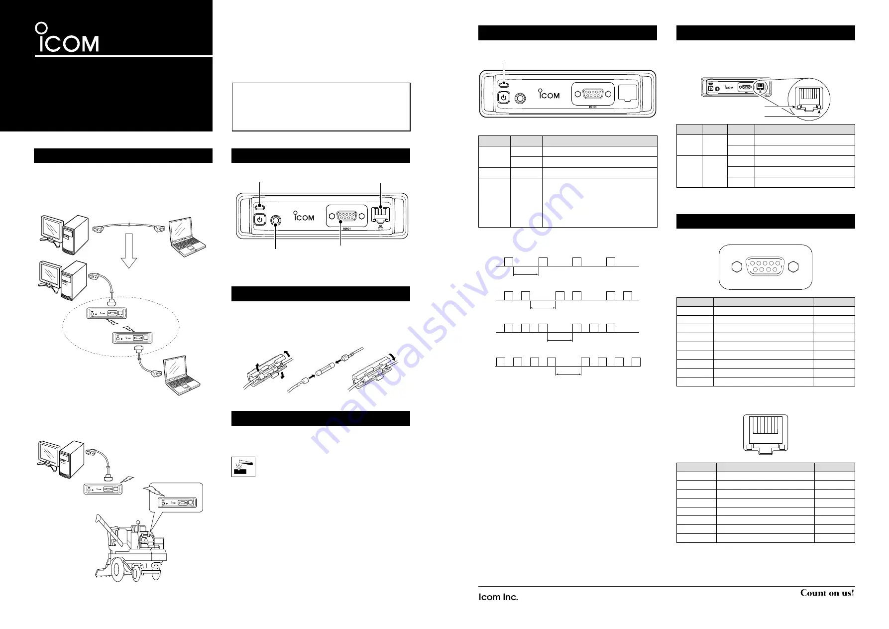
PANEL DESCRIPTION
Status indicator
Cloning jack RS-232C connector
Ethernet port*
* The Ethernet port may not be installed, depending on the transceiv-
er version.
ABOUT THE STATUS INDICATOR
The Status Indicator indicates various transceiver status.
Status indicator
Color
Status
Description
Green
Lit
Power ON and standing by
Blinking
Receiving data
Red
Lit
Transmitting data
Orange
Blinking
A problem occurred.
The cause may differ, depending on
the blinking pattern.
See the diagram below for de-
tails about the blinking patterns and
causes.
• Reducing the transmission output to protect the final am-
plifier
O
O
O
O
500 ms*
• PLL unlock
O
O
O
O
O
O
500 ms*
• Overvoltage
O
O
O
O
O
O
500 ms*
• Low voltage
O
O
O
O
O
O
O
O
500 ms*
*Approximately (ms: millisecond)
O=Orange
If the Status Indicator blinks orange, contact your dealer or
system integrator.
CLEANING
If the transceiver becomes dusty or dirty, wipe it clean with a
soft, dry cloth.
DO NOT
use harsh solvents such as benzine or al-
cohol, as they may damage the transceiver surfac-
es.
ABOUT ETHERNET PORT INDICATORS
The Ethernet port indicators indicate the status of the net-
work and data.
* The Ethernet port may not be installed, depending on the transceiv-
er version.
SPEED
LINK/ACT
Color Status
Description
SPEED Orange Not lit
Connected to 10BASE-T
Lit
Connected to 100BASE-TX
LINK/
ACT
Green Not lit
Not connected to the network
Lit
Connected to the network
Blinking Receiving and Transmitting data
PIN ASSIGNMENT
• RS-232C connector
Pin No.
Line Name
I/O
1
(No connection)
-
2
RxD
OUT
3
TxD
IN
4
DTR
IN
5
GND
-
6
(No connection)
-
7
RTS
IN
8
CTS
OUT
9
(No connection)
-
• Ethernet port
* The Ethernet port may not be installed, depending on the transceiv-
er version.
Pin No.
Line Name
I/O
1
TX+
OUT
2
TX-
OUT
3
RX+
IN
4
(No connection)
-
5
(No connection)
-
6
RX-
IN
7
(No connection)
-
8
(No connection)
-
1
8
1
5
6
9
#4-40
inch screw
#4-40
inch screw
ABOUT IC-F5122DD/IC-F6122DD
Normally packet data from data software or hardware sensor
are exchanged between 2 computers or equivalent devices
using RS-232C serial cable or ETHERNET cable.
A pair of IC-F5122DD/IC-F6122DD is replacing part of com-
munication cable with a wireless connection.
Example of use:
RS-232C
Straight cable
RS-232C Cross cable
RS-232C
Straight cable
RF Link
Sending position,
environment,
instrument,
or control information
Collecting position,
environment,
instrument,
or control information


