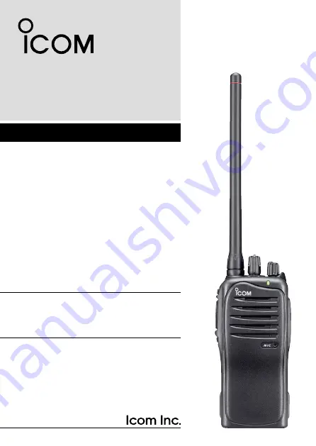
INSTRUCTION MANUAL
This device complies with Part 15 of the FCC Rules. Operation is subject to the condition that this device does not cause harmful inter-ference.
UHF TRANSCEIVERS
iF4011
iF4013
VHF TRANSCEIVERS
iF3011
iF3013
Page 1: ...MANUAL This device complies with Part 15 of the FCC Rules Operation is subject to the condition that this device does not cause harmful inter ference UHF TRANSCEIVERS iF4011 iF4013 VHF TRANSCEIVERS iF...
Page 2: ...ting Compliance with FCC Guidelines for Human Exposure to Radio Frequency Electromagnetic Fields American National Standards Institute C95 1 1992 IEEE Standard for Safety Levels with Respect to Human...
Page 3: ...equirements are not exceeded To provide the recipients of your transmission the best sound qual ity hold the antenna at least 5 cm 2 inches from your mouth and slightly off to one side The information...
Page 4: ...LICIT DEFINITIONS WORD DEFINITION RDANGER Personal death serious injury or an explo sion may occur RWARNING Personal injury fire hazard or electric shock may occur CAUTION Equipment damage may occur N...
Page 5: ...may be damaged DO NOT push PTT when not actually desiring to transmit DO NOT use or place the transceiver in direct sunlight or in areas with temperatures below 30 C 22 F or above 60 C 140 F DO NOT m...
Page 6: ...grammable function keys 9 3 CONVENTIONAL OPERATION 12 15 Turning power ON 12 Channel selection 12 Receiving and transmitting 13 Setting the squelch level 15 4 SIGNALING OPERATIONS 16 17 Call procedure...
Page 7: ...s The following accessories are supplied Flexible antenna Battery pack Battery carger with AC adapter Belt clip Jack cover with screws This illustration is described with the VHF type 1 2 3 4 5 6 7 8...
Page 8: ...ssory attachments D Flexible antenna Connect the supplied flexible antenna to the antenna connector CAUTION NEVER HOLD the antenna when carrying the transceiver Transmitting without an antenna may dam...
Page 9: ...n makes a click sound To release the battery pack Push the battery release button in the direction of the arrow w as shown below The battery pack is then released NEVER release or attach the battery p...
Page 10: ...aker microphone is not used To attach the jack cover q Attach the jack cover to the SP MIC connector w Tighten the screws To detach the jack cover e Unscrew the screws with a phillips screwdriver r De...
Page 11: ...ide the belt clip in the direction of the arrow until the belt clip is locked and makes a click sound To detach the belt clip q Release the battery pack if it is attached w Pinch the clip q and slide...
Page 12: ...top and side panels Microphone Speaker r w e y u i t q q CHANNEL SELECTOR Rotate the channel selector to select the pre programmed mem ory channels w VOLUME CONTROL VOL Rotate to turn the power ON OFF...
Page 13: ...MIC Connects the optional speaker microphone earphone etc SP MIC jack cover NOTE Attach the SP MIC jack cover when the optional equip ment is not used p 4 t DEALER PROGRAMMABLE KEY Lower The desired f...
Page 14: ...ile transmitting a signal RX Turns Green while receiving a signal For IC F3013 IC F4013 only Call LED ON When receiving a matched 2 5 tone Call LED Blink When receiving a matched 2 5 tone Fast Slow sc...
Page 15: ...ned ON push to pause the scanning operation The paused scan restarts after the spec ified time period has passed SCAN B KEY Push to start and cancel scanning operation In case of transmis sion during...
Page 16: ...ver communication WIDE NARROW KEY Push to select the IF bandwidth to wide The wide passband width can be selected from 25 or 20 kHz using the optional cloning software PMR operation only Ask your deal...
Page 17: ...L KEY Push to transmit the programmed DTMF code CALL KEYS Push to transmit a 2 5 tone code Call transmission is necessary before you call another station depend ing on your signalling system Call A an...
Page 18: ...o se lect the desired operating channel in sequence or push one of MR CH 1 to MR CH 4 key to select a channel di rectly AUTOMATIC SCAN TYPE Channel setting is not necessary for this type When turning...
Page 19: ...t the audio output level to a comfort able listening level Transmitting Wait for the channel to become clear to avoid interference q While pushing and holding PTT speak into the microphone at a normal...
Page 20: ...condition The channel is busy Un matched or matched CTCSS is received The selected channel is a receive only channel Time out timer After continuous transmission for the pre programmed time period th...
Page 21: ...ile pushing PTT and Lower rotate VOL to turn the power ON to enter the squelch level adjust ment mode w Push Upper to increase the squelch level tight squelch or Lower to decrease the squelch level lo...
Page 22: ...unwanted stations from contacting you q Select the desired TX code channel or 2 5 tone code according to your System Operator s instructions This may not be necessary depending on programming w Push...
Page 23: ...ted channel If you want to cancel the emergency call push and hold the key again before transmitting the call The emergency call can be transmitted without a beep emission and the LCD indication if Em...
Page 24: ...n severely impacted or dropped or if the battery has been subjected to heavy pressure Battery damage may not be visible on the outside of the case Even if the surface of the battery does not show crac...
Page 25: ...see a doctor immediately WARNING Immediately stop using the battery if it emits an ab normal odor heats up or is discolored or deformed If any of these conditions occur contact your Icom dealer or di...
Page 26: ...ents the safety protection circuit in the battery will activate causing the bat tery to stop charging WARNING DO NOT charge or leave the battery in the battery charger beyond the specified time for ch...
Page 27: ...versions or the DC power cable OPC 515L CP 17L is additionally required AC adapter Not supplied with some versions Optional OPC 515L for 13 8 V power source or CP 17L for 12 V cigarette lighter socket...
Page 28: ...supplied with some versions or the DC power cable OPC 515L CP 17L is additionally required AC adapter Not supplied with some versions Optional OPC 515L for 13 8 V power source or CP 17L for 12 V ciga...
Page 29: ...nnect the AD 106 charger adapter and the BC 119N BC 121N as below then install the AD 106 into the holder space of the BC 119N or BC 121N with the supplied screws Desktop charger adapter Connectors Pl...
Page 30: ...r not supplied with some versions or the DC power cable OPC 515L CP 17L AD 106 charger adapter is installed in BC 119N AC adapter Not supplied with some versions Optional OPC 515L for 13 8 V power sou...
Page 31: ...ollowing items are additionally required Six AD 106 An AC adapter BC 157 or the DC power cable OPC 656 AC adapter Purchase separately AD 106 charger adapters are installed in each slot DC power cable...
Page 32: ...lose r Hook the battery cover release hook until it makes a click sound t Fig 3 CAUTION When installing batteries make sure they are all the same brand type and capacity Also do not mix new and old ba...
Page 33: ...27 6 BATTERY CASE 1 2 3 4 5 6 7 8 9 10 11 12 13 14 15 16 17 18 19 20 q BP 240 w Fig 1 Fig 2 Fig 3 e r t...
Page 34: ...IP MB 93 contents Qty q Belt clip 1 w Base clip 1 To attach q Release the battery pack if it is attached p 3 w Slide the base clip in the direction of the arrow until the base clip is locked and makes...
Page 35: ...the transceiver into the belt clip until the base clip inserted fully into the groove r Once the transceiver is locked in place it swivels as illustrated below Once the transceiver is locked in place...
Page 36: ...30 7 SWIVEL BELT CLIP To detach q Turn the transceiver upside down in the direction of the arrow and pull out from the belt clip...
Page 37: ...n of the arrow w q w CAUTION HOLD THE TRANSCEIVER TIGHTLY WHEN HANGING OR DETACHING THE TRANSCEIVER FROM THE BELT CLIP Otherwise the transceiver may not be attached to the holder or swivel properly if...
Page 38: ...6 charger adapter BC 145S ac adapter For rapid charging of battery packs An AC adapter is supplied with the charger depending on versions Charging time approx 3 hours when BP 232N is attached BC 121N...
Page 39: ...the battery pack through a 12 V cigarette lighter socket For BC 119N OPC 515L OPC 656 dc power cables Allows charging of the battery pack using a 13 8 V power source instead of the AC adapter OPC 515L...
Page 40: ...belt VS 1L vox ptt case HS 94 HS 95 HS 97 headset VS 1L VOX PTT switch box for hands free operation etc HS 94 Ear hook type HS 95 Neck arm type HS 97 Throat microphone Icom optional equipment are desi...
Page 41: ...rns to receive when you stop speaking Features Straight type head SP MIC plug equipped Water resistant construction Durable construction Equipped with a PTT switch and revolving clip MIC VOX gain adju...
Page 42: ...harmful interference to radio communications However there is no guarantee that interference will not occur in a particular installation If this equipment does cause harmful interference to radio or t...
Page 43: ...MEMO 1 2 3 4 5 6 7 8 9 10 11 12 13 14 15 16 17 18 19 20...
Page 44: ...MEMO...
Page 45: ...MEMO 1 2 3 4 5 6 7 8 9 10 11 12 13 14 15 16 17 18 19 20...
Page 46: ...MEMO...
Page 47: ...MEMO 1 2 3 4 5 6 7 8 9 10 11 12 13 14 15 16 17 18 19 20...
Page 48: ...1 1 32 Kamiminami Hirano ku Osaka 547 0003 Japan A 6768H 1EX Printed in Japan 2009 Icom Inc Printed on recycled paper with soy ink...