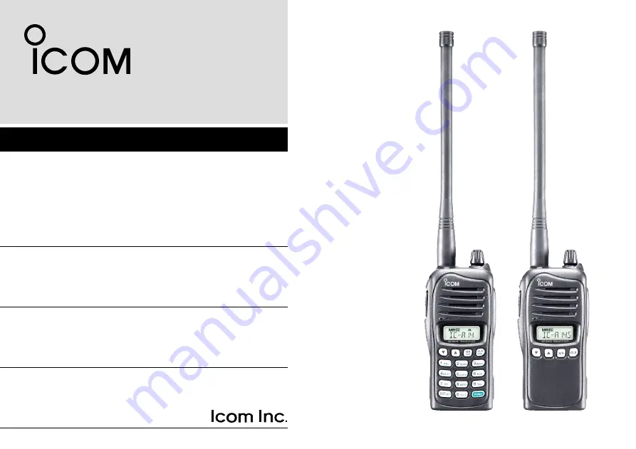
INSTRUCTION MANUAL
iA14
iA14S
VHF AIR BAND TRANSCEIVER
This device complies with Part 15 of the FCC Rules. Operation is subject to the condition that this device does not cause harmful interference.
Y
IC-A14
IC-A14S
Page 1: ...CTION MANUAL iA14 iA14S VHF AIR BAND TRANSCEIVER This device complies with Part 15 of the FCC Rules Operation is subject to the condition that this device does not cause harmful interference YIC A14 YIC A14S ...
Page 2: ...ons for the IC A14 IC A14S vhf air band transceiver EXPLICIT DEFINITIONS WORD DEFINITION RDANGER Personal death serious injury or an explosion may occur RWARNING Personal injury fire hazard or electric shock may occur CAUTION Equipment damage may occur NOTE If disregarded inconvenience only No risk of per sonal injury fire or electric shock SUPPLIED ACCESSORIES The following accessories are suppli...
Page 3: ... caps or in an explosive atmosphere CAUTION DO NOT use harsh solvents such as Benzine or alcohol to clean the transceiver because they can damage the transceiver s surfaces DO NOT place the transceiver in direct sunlight or in areas with temperatures below 10 C 14 F or above 60 C 140 F KEEP the transceiver in a secure place to prevent use by unauthorized persons KEEP the transceiver away from the ...
Page 4: ...t This equipment generates uses and can radiate radio frequency energy and if not installed and used in accordance with the instruction manual may cause harmful interference to radio communications Operation of this equipment in a residential area is likely to cause harmful interference in which case the user will be required to correct the interference at his own expense CAUTION Changes or modifi...
Page 5: ... the memory contents Available with the IC A14 only 17 5 SCAN OPERATION 18 20 Scan types 18 COM band scan 18 Memory scan 19 Weather channel scan Available with the IC A14 only 19 TAG channel setting 20 6 OTHER FUNCTIONS 21 26 Home function 21 Accessing the 121 5 MHz emergency frequency Selectable on only the IC A14 21 Key touch beep tone 22 ANL function 22 Weather channel operation Available with ...
Page 6: ...setting ON or OFF p 20 r PTT SWITCH PTT Hold down to transmit release to receive t SQUELCH UP DOWN KEYS SQLY SQLZ p 9 Push either key to select the squelch level 10 squelch levels 1 10 and squelch open 0 are selectable y UP DOWN KEYS Y Z Push to change or select the operating frequency memory channel Set mode setting and so on p 8 While scanning push to change the scanning direction pp 18 19 For t...
Page 7: ...LEAR HOME SWITCH CLR HOME Push to select the frequency mode p 8 Hold down for 2 seconds to reset the transceiver to the user default state without changing the memory con tents Home function p 21 0 EXTERNAL SPEAKER AND MICROPHONE JACKS MIC SP p 39 If desired connects the optional speaker microphone or a headset using the optional OPC 499 HEADSET ADAPTER NEVER connect an optional speaker microphone...
Page 8: ...2 Inputs 4 G H or I when entering memory names p 15 After pushing FUNC turns the weather alert function ON or OFF p 23 Inputs digit 5 for frequency entry or memory channel selection pp 8 12 Inputs 5 J K or L when entering memory names p 15 After pushing FUNC enters duplex transmit fre quency entry mode during NAVI band operation p 24 Inputs digit 6 for frequency entry or memory channel selection p...
Page 9: ...pace or when entering memory names p 15 After pushing FUNC selects the emergency fre quency 121 500 MHz p 21 Sets the numeral entry for frequency or memory channel numbers Enters consecutive zero into the remaining digits pp 8 12 After pushing FUNC hold down for 1 second to entering into set mode p 25 Push to activate the function then push another key to access its secondary function When the fun...
Page 10: ...le setting the duplex frequency u ANL ICON p 22 Appears when the ANL Automatic Noise Limiter func tion is in use i WEATHER ALERT ICON IC A14 only p 23 Appears when the weather alert function is in use o LOCK ICON p 9 Appears when the lock function is in use 0 LOW BATTERY ICON p 11 Appears when the battery is nearing exhaustion The attached battery pack requires recharging when this icon appears Bl...
Page 11: ... the transceiv er may be damaged D Belt clip Conveniently attaches to your belt To attach the belt clip q Remove the battery pack if it is attached w Slide the belt clip in the direction of the arrow until the belt clip is locked and makes a click sound To detach the belt clip q Remove the battery pack if it is attached w Pinch the clip q and slide the belt clip in the direction of the arrow w q w...
Page 12: ... be detached NEVER release or attach the battery pack when the trans ceiver is wet or soiled This may result water or dust get ting into the transceiver battery pack and may result in the transceiver being damaged 2 ACCESSORY ATTACHMENT q w Battery release button Turn OFF the transceiver power by rotating VOL before at taching or detaching the battery pack For your information If the transceiver p...
Page 13: ... only q Rotate VOL to turn ON power then push CLR to select the frequency mode if a memory CH number or WX CH number appears on the function display w Push 5 appropriate digit keys to input the frequency Push 1 as the 1st digit When a wrong digit is input push CLR to clear then repeat step w again Push ENT to enter consecutive zero digits Only 2 5 7 or 0 can be entered as the 5th and final digit E...
Page 14: ...The icon appears while the squelch is open w Wait for 1 second to return to the previous display Lock function The lock function prevents accidental frequency changes or accidental function activation q Push to turn ON the lock function The icon appears w To turn OFF the function hold down for 2 seconds The icon disappears 9 3 BASIC OPERATION SQLY SQL 0 Squelch open SQLZ Appears while the key lock...
Page 15: ...4 only COM band frequency range 118 00 136 975 MHz w Hold down PTT to transmit The icon appears e Speak into the microphone at a normal voice level DO NOT hold the transceiver too close to your mouth or speak too loudly This may distort the signal r Release PTT to receive NOTE About Time Out Timer function To prevent prolonged transmission according to regula tory requirements the IC A14 S has a T...
Page 16: ...as an LCD backlight for convenience during night time operation Push LIGHT to turn the LCD backlight ON or OFF IMPORTANT Turn OFF the LCD back light when no backlight is necessary Low battery icon The low battery icon appears or blinks when the battery power has decreased to a specified level The attached bat tery pack or battery case requires recharging or the battery case cells need replacing If...
Page 17: ...ting to select the desired memory channel num ber then push ENT The memory channel number is briefly displayed then the entered frequency or memory name if entered is displayed If no memory channel is entered in the selected BANK no memory channel can be selected Memory bank selection Available with the IC A14 only A total of 200 memory channels in the IC A14 are divided into bank up to 10 banks a...
Page 18: ... icon blinks r Push Y Z to select a memory channel number Push FUNC then push BANK 3 to enter the bank selection mode and push Y Z or an appropriate digit keys 0 9 then push ENT to select the BANK number if desired t Push ENT to program the entry and return to the fre quency mode 13 4 MEMORY OPERATION EXAMPLE Entering WX 05 into memory channel 9 in memory BANK 3 Blinks when the select memory write...
Page 19: ...sh Y Z to select the desired memory channel num ber t Hold down MR for 1 second to set the entry and return to the frequency mode Blinks when the select memory write mode is selected No frequency is displayed when a blank channel is selected EXAMPLE Entering 123 450 MHz into memory channel 51 Push or Push or Briefly appears Hold down for 1 second Push Hold down for 1 second 1 2 3 4 5 6 7 8 9 10 11...
Page 20: ...ckwards use Y Z The cursor automatically moves forward when a different key is pushed To erase a character overwrite with a space displayed as _ y Push ENT to enter the name and frequency at the same time Return to the frequency display If no name is entered the entered frequency is displayed To clear the entered memory names push CLR before push ing ENT For the IC A14S t Push Y Z several times to...
Page 21: ... MR for 1 second again r Push MR momentarily to select memory name entry mode t Perform the steps t and y described at left page in For the IC A14S to enter the desired memory name Copying memory contents This function copies a memory channel s contents into the frequency mode This is useful when searching for signals around a memory channel s frequency q Push MR to select the memory mode w Select...
Page 22: ...le with the IC A14 only Unwanted memory channels can be cleared q Select the desired memory channel to be cleared p 12 Select the desired bank if desired p 12 w Push FUNC then hold down CLR for 1 second appears briefly then the next selectable channel appears ...
Page 23: ...can pauses until the signal dis appears To change the scanning direction push Y Z r To stop the scan push CLR WEATHER CHANNEL SCAN Repeatedly scans all TAG weather channels Weather channels are available for the IC A14 only COM BAND SCAN Repeatedly scans all frequencies over the entire COM band 108 00 MHz Scan Jump 118 00 MHz 136 975 MHz MEMORY SCAN Repeatedly scans se lected memory bank s all TAG...
Page 24: ... enter the memory mode For the IC A14 select the desired BANK if desired p 12 w Push SQLY SQLZ to set the squelch level to the point where noise just disappears For the IC A14 e Push FUNC then push SCAN 2 to start the scan When a signal is received the scan pauses until the signal dis appears To change the scanning direction push Y Z For the IC A14S e Hold down Y Z for 1 second to start the scan W...
Page 25: ...ed w Select the desired memory weather channel to be a TAG channel Select the desired BANK if desired e Push FUNC then push TAG 9 to set a TAG TAG appears Non TAG channels are skipped during scan r To cancel the TAG setting repeat above steps For the IC A14S q Push MR to select the memory mode w Select the desired memory channel to be a TAG chan nel e Hold down LIGHT for 2 seconds to set a TAG r T...
Page 26: ...rophone usage Time Out timer setting The default settings can be modified to suits your preference using with the optional cloning software CS A14 Hold down CLR for 2 seconds to return the transceiver into the default setting Accessing the 121 5 MHz emergency frequency Selectable on only the IC A14 The IC A14 can quickly be set to the 121 5 MHz emergency frequency This function can be activated ev...
Page 27: ...the frequency mode ANL function The ANL Automatic Noise Limiter function reduces noise components on received signals such as those caused by engine ignition systems For the IC A14 Push FUNC then push ANL 1 to turn the ANL function ON or OFF The ANL icon appears when the ANL function is ON For the IC A14S q Rotate VOL to turn the transceiver power OFF w While holding down Y Z rotate VOL to enter t...
Page 28: ...requency mode D Setting weather alert function An NOAA broadcast station transmits a weather alert tone before any important weather announcements When the weather alert function is turned ON the transceiver detects the alert and sounds a beep tone until the transceiver is op erated The previously selected used weather channel is checked any time during standby or while scanning Push FUNC then pus...
Page 29: ...eturns to the NAVI band frequency D Using the duplex function q Set the desired frequency in the NAVI band NAVI band frequency range 108 00 117 975 MHz w Push FUNC then push DUP 6 to turn the duplex func tion ON The DUP icon appears e Hold down PTT to transmit on the pre entered transmit frequency r Release PTT to return to receive t Push FUNC then push DUP 6 to cancel the function The DUP icon di...
Page 30: ...SET ENT for 1 second to also enter the Set mode For your information The default value of the Set mode items can be changed with the optional CS A14 cloning software The default settings are recalled by the Home function D Set mode items ANL ANL function selectable in only the IC A14S Turns the ANL Automatic Noise Limiter function ON or OFF The ANL reduces received noise components such as those c...
Page 31: ...l microphone when PTT is pushed TOT Time out timer Sets the time out timer period to prevent prolonged transmis sions according to regulatory requirements This timer cuts OFF a transmission after the set time period Set the timer to between 20 and 180 seconds in 10 second steps or to OFF Ask your dealer for local regulation details 1 2 3 4 5 6 7 8 9 10 11 12 13 14 15 16 17 18 19 ...
Page 32: ...ode Dispose of an used battery pack in accordance with local regulations RDANGER NEVER solder the battery terminals or NEVER modify the battery pack This may generate heat in the bat tery and the battery pack may burst emit smoke or catch fire RDANGER Use the battery only with the transceiver for which it is specified Never use a battery with any other equipment or for any purpose that is not spec...
Page 33: ... to be fully charged the oper ating time of the transceiver may become short when Approximately five years have passed since the battery was manufactured The battery has been repeatedly charged D Charging caution RDANGER NEVER charge the battery pack in areas with extremely high temperatures such as near fires or stoves inside a sun heated vehicle or in direct sunlight In such en vironments the sa...
Page 34: ...er Charging period Approximately 12 hours for the BP 232N Approximately 13 5 hours for the BP 232H Charging indicator color information Orange While charging Green When charging is completed Orange or green blink The battery pack or the charger has a problem CAUTION DO NOT modify the CP 22 A modification could cause a fire or electric shock BE CAREFUL not to cut or fray the CP 22 s power cable whe...
Page 35: ...apter may be supplied with BC 119N depending on the charger versions or the OPC 515L DC power cable 7 BATTERY PACKS AND CASE Screws supplied with AD 106 AD 106 Connectors Plugs q w The AD 106 charger adapter is installed in the BC 119N Power adapter Not supplied with some versions Optional OPC 515L for 13 8 V power source can be used instead of the power adapter Transceiver Battery pack Turn power...
Page 36: ...o do not mix new and old bat tery cells together Install conventional alkaline cells only Other type of batter ies such as Ni Cd Ni MH Li ion cannot be used Remove the alkaline cells when leaving the battery case un used for long time Keep battery contacts clean It s a good idea to occasionally clean the battery terminals Alkaline cells have a shorter operating time compared to Li ion battery cell...
Page 37: ...ad use something relatively flat like the edge of a coin or the tip of a screwdriver to carefully release the latch w Install 6 AA LR6 size alkaline cells Install the conventional alkaline cells only Be sure to observe the correct polarity e Attach the cover then close And lock the latch until it makes a click sound CAUTION When installing batteries make sure they are all the same brand type and c...
Page 38: ...e Slide out the battery case s battery release button in the di rection of the arrow q and then push the release button in the direction of the arrow w as shown in the illustration below The battery pack is then released q w NEVER release or attach the battery case when the trans ceiver is wet or soiled This may result water or dust get ting into the transceiver battery case and may result in the ...
Page 39: ... sub transceivers e While holding down MR rotate VOL to enter the clon ing mode for the master transceiver only CLONE appears and the transceivers enter the clone standby condition e Push PTT on the master transceiver CL OUT appears in the master transceiver s display CL IN automatically appears on the sub transceiver s display r When the cloning is finished turn OFF power then turn ON again to ex...
Page 40: ...ING CABLE Consult the CS A14 CLONING SOFTWARE HELP file for details D Cloning error When the display as below appears a cloning error has oc curred In this case both transceivers automatically return to the clone standby condition and cloning must be repeated Microsoft Windows and Windows Vista are registered trademarks or trademarks of Microsoft Corporation in the U S A and or other countries 35 ...
Page 41: ...harge the battery pack pp 29 31 The operating frequency or The lock function is activated Hold down for 2 seconds to turn the Lock p 9 memory channel can not function OFF be changed Scan does not start All memory channels in the selected bank are Set the TAG settings of desired channels p 20 not programmed as TAG channels The Squelch is open Set the squelch level tighter p 9 There is not more than...
Page 42: ...0 Frequency stability 5 ppm Audio harmonic distortion Less than 10 at 60 modulation Hum and noise ratio More than 35 dB Spurious emissions More than 46 dB except operating frequency 62 5 kHz range External MIC connector 3 conductor 2 5 d mm 1 10 150 Ω D Receiver Receive system Double conversion superhetero dyne Intermediate frequencies 1st 46 35 MHz 2nd 450 kHz Sensitivity COM band 6 dB S N 6 dBµ ...
Page 43: ...HONE HM 173 speaker microphone Combination speaker and microphone D BELT CLIPS MB 94 belt clip Alligator type belt clip MB 96F leather belt hanger Attaches with the supplied belt clip Fixed type D DC CABLES CP 22 cigarette lighter cable DC DC converter is built in Charges the battery pack using 12 24 V DC power source instead of the power adapter for BC 171 179 OPC 515L dc power cable for BC 119N ...
Page 44: ...ed voice to the headset for monitoring See n Side tone function p 11 when setting the side tone level PTT OPC 499 Transceiver PTT switch HEADSET Purchase separately Use a PTT switch with a 3 5 mm 1 8 inch diameter plug if required NOTICE Some headsets do not work properly when used with the IC A14 S Therefore ask your dealer for details about headsets compatible with the IC A14 S ...
Page 45: ...guidelines DO NOT operate the radio without a proper antenna attached as this may damaged the radio and may also cause you to exceed FCC and IC RF exposure limits A proper antenna is the antenna supplied with this radio by the manufacturer or antenna specifically authorized by the manufacturer for use with this radio DO NOT transmit for more than 50 of total radio use time 50 duty cycle Transmitti...
Page 46: ...dio et causer une exposi tion supérieure aux limites établies par la FCC et d IC L antenne appro priée est celle qui est fournie avec cette radio par le fabricant ou une antenne spécialement autorisée par le fabricant pour être utilisée avec cette radio NE PAS émettre pendant plus de 50 du temps total d utilisation de l appareil 50 du facteur d utilisation La notion 50 du facteur d utilisation s a...
Page 47: ...42 MEMO 1 2 3 4 5 6 7 8 9 10 11 12 13 14 15 16 17 18 19 ...
Page 48: ...1 1 32 Kamiminami Hirano ku Osaka 547 0003 Japan Printed on recycled paper with soy ink A 6631H 1EX e Printed in Japan 2007 2016 Icom Inc ...