

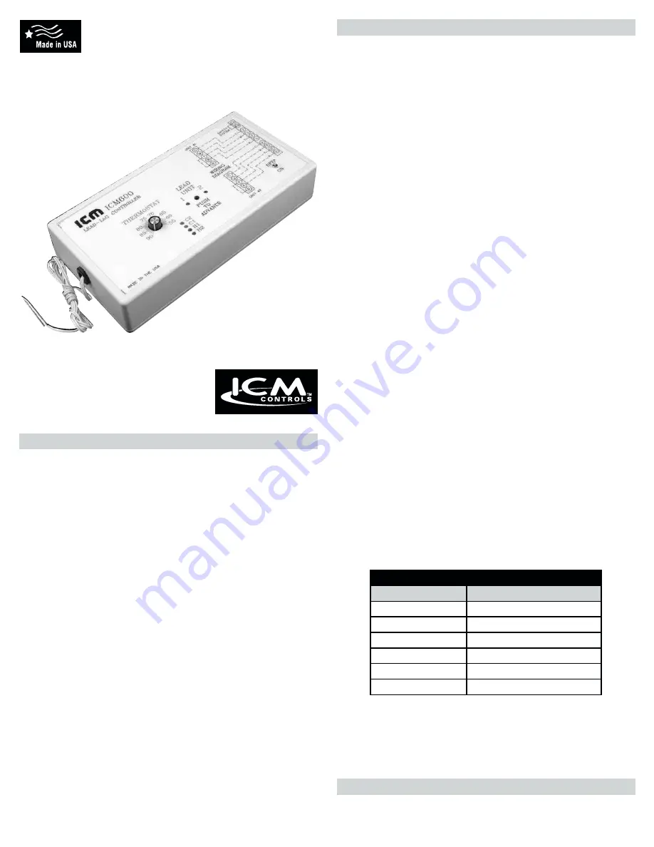
ICM600/ICM601
Lead Lag Controller
Microprocessor controlled regulation for
one or two heating/cooling systems to
provide a constant temperature.
Specifications
Caution
Installation of the ICM600/ICM601 shall be performed by trained
technicians only. Adhere to all local and national electric codes.
Disconnect all power to the system before making any connections
.
ELECTRICAL
Input
•
Nominal Voltage:
18 to 30 VAC
•
Frequency:
50 to 60 Hz
Output
•
Type:
Triac
•
Number:
Four (4)
•
Rating:
2 amps per output @ nom. 24 VAC
OPERATIONAL
Heat/Cool Staging
•
First Stage Heat (H1):
Deadband setting above thermostat setpoint (C1)
•
Second Stage Heat (H2):
2°F above H1
•
First Stage Cool (C1):
Equal to the thermostat setpoint
•
Second Stage Cool (C2):
2°F below C1
Deadband
•
Adjustable:
2°F to 20°F
Anti-short Cycle Protection
•
Stage 1:
Three (3) minutes
•
Stage 2:
Four (4) minutes
Setpoint
•
Adjustable:
55°F to 90°F
Advance Sequencer
•
Pin selectable:
Alternates every 1, 3, 7, 14, or 28 days, or fixed
• Manual
ADVANCE
pushbutton initializes sequence period
Mode Memory
• On power loss, system “remembers” which mode it was in
Test Modes
• Thermistor bypass calibration mode jumper
• Accelerated test mode jumper
Call Lights (LEDs)
•
Green LEDs:
Call for COOL (C1 & C2)
•
Red LEDs:
Call for HEAT (H1 & H2)
Main steps for programming the Lead-Lag Controller:
1. Temperature Selection Pot
2. Deadband Pot
3. Advance Sequencer
4. Advance (Override) Switch
5. Test Mode Jumper
1. Temperature Selection Pot:
This selection pot is the temperature above which the cooling cycle
begins. In cooling mode, the green “call for cool” indicator light - C1 (and
C2 if second stage cooling is required) stays on. Each light corresponds
to one stage of cooling. The temperature spacing between these lights is
approximately 2°F. In heating mode, the red “call for heat” indicator lights,
H1 and H2, operate similarly. The temperature spacing between cooling
and heating modes is the deadband setting.
2. Deadband Pot:
The deadband is the range where neither heating nor cooling is necessary.
The deadband adjustment moves the heating setpoints in relation to
the cooling setpoints. At its minimum position (counterclockwise) the
deadband is 2°F. At its maximum position the deadband is 20°F.
3. Advance Sequencer:
For 2-stage alternating installations, the advance sequencer demands
equal operating time from
groups A and B. Select the time interval by placing a jumper over one
of the jumper pair posts. The jumper labeled “0” disables the advance
timing; use it when the controller is connected to a single heating/cooling
group, or when alternating operation between two heater/cooler groups
is not desired. In test mode (when the test mode jumper is installed), the
advance times are accelerated (see the values shown in the Test Mode
Advance Time Table). In normal mode (test mode jumper removed),
advance times are in days as printed on the printed circuit board
(i.e. 1, 3, 7, 14, 28). Setting the controller for 7 days is appropriate for most
installations.
4. Advance (Override) Switch:
The advance switch is a pushbutton switch provided to override the timing
and instantaneously switch the lead group. The two red LEDs indicate
which group will start first. The LED on the left is group A and the LED
on the right is group B. Pressing the switch not only changes the lead
group, but also restarts the anti-short cycle delay on make, and sets the
main timer to zero. This feature can be used to reset the timer so the next
advance time will be known.
5. Test Mode Jumper:
The test mode provides for accelerated testing of the advance (override)
function of the controller and the output delay on make times. When the
test mode jumper is installed, the advance time conversion is from days to
seconds. Accelerated anti-short cycle delay on make times are 1 second
for stage one heating/cooling, and 4 seconds for stage two heating/
cooling. Test mode advance times are as specified in the table below.
Operation
TEST MODE ADVANCE TIME TABLE
Jumper Number
Advance Time (seconds)
0
• no advance •
1
1
3
3
7
7
14
14
28
28
For information on our complete range of American-made
products — plus wiring diagrams, troubleshooting tips and
more, visit us at
www.icmcontrols.com
APPLICATION GUIDE