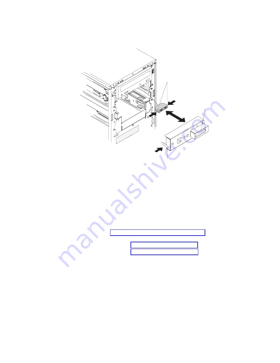
Installing
the
front
USB
connector
assembly
To
install
the
front
USB
connector
assembly,
complete
the
following
steps.
Spring clips
Orientation tab
Retaining tab
1.
Carefully
insert
the
front
USB
connector
assembly
cable
into
the
opening
in
the
front
of
the
chassis.
2.
Squeeze
the
spring
clips
on
the
sides
of
the
front
USB
connector
assembly;
then,
from
the
rear
of
the
power
switch/LED
bracket,
insert
the
assembly
into
the
opening
in
the
front
of
the
bracket
and
release
the
spring
clips.
Note:
The
orientation
tab
in
the
center
of
the
connector
is
keyed
to
a
notch
in
the
top
of
the
opening.
3.
Place
the
right
side
of
the
power
switch/LED
bracket
into
the
opening
in
the
chassis
and
rotate
the
bracket
to
the
left
until
the
retaining
tab
clicks
into
place.
4.
Route
the
front
USB
connector
assembly
cable;
then,
connect
it
to
the
system
board
(see
for
the
location
of
the
front
USB
connector).
5.
Install
the
bezel
(see
6.
Install
the
cover
(see
7.
Reconnect
the
external
cables
and
power
cords
to
the
server;
then,
connect
the
power
cords
to
electrical
outlets.
8.
Turn
on
the
attached
devices;
then,
turn
on
the
server.
Chapter
4.
Removing
and
replacing
server
components
77
Summary of Contents for xSeries 100
Page 1: ...IBM xSeries 100 Type 8486 Problem Determination and Service Guide...
Page 2: ......
Page 3: ...IBM xSeries 100 Type 8486 Problem Determination and Service Guide...
Page 8: ...vi IBM xSeries 100 Type 8486 Problem Determination and Service Guide...
Page 28: ...12 IBM xSeries 100 Type 8486 Problem Determination and Service Guide...
Page 106: ...90 IBM xSeries 100 Type 8486 Problem Determination and Service Guide...
Page 110: ...94 IBM xSeries 100 Type 8486 Problem Determination and Service Guide...
Page 120: ...104 IBM xSeries 100 Type 8486 Problem Determination and Service Guide...
Page 125: ......
Page 126: ...Part Number 31R2070 Printed in USA 1P P N 31R2070...


