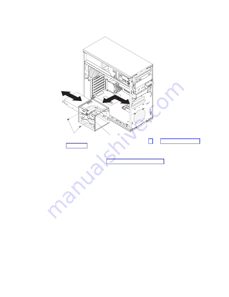
Removing
a
drive
in
bay
4
or
5
To
remove
a
drive
from
bay
4
or
5,
complete
the
following
steps.
Locking lever
Screws
1.
Read
the
safety
information
that
begins
on
page
and
2.
Turn
off
the
server
and
all
peripheral
devices;
then,
disconnect
the
power
cords
and
all
external
cables.
3.
Remove
the
cover
(see
4.
Disconnect
the
cables
from
the
drive
to
be
removed
or
from
both
drives
in
the
drive
cage,
if
two
drives
are
installed.
Attention:
Make
sure
that
you
do
not
hit
the
microprocessor
fan
sink
when
removing
the
drive
cage.
5.
Remove
the
drive
cage:
a.
Move
the
locking
lever
on
the
drive
cage
to
the
Unlock
position.
b.
Firmly
grasp
the
drive
cage
and
slide
it
toward
the
rear
of
the
server
until
it
disengages
from
the
chassis.
c.
Lift
the
drive
cage
out
of
the
server.
6.
Remove
the
four
screws
(two
on
each
side)
that
secure
the
drive
to
the
drive
cage
and
slide
the
drive
out
of
the
cage.
7.
If
you
are
instructed
to
return
the
drive,
follow
all
packaging
instructions,
and
use
any
packaging
materials
for
shipping
that
are
supplied
to
you.
72
IBM
xSeries
100
Type
8486:
Problem
Determination
and
Service
Guide
Summary of Contents for xSeries 100
Page 1: ...IBM xSeries 100 Type 8486 Problem Determination and Service Guide...
Page 2: ......
Page 3: ...IBM xSeries 100 Type 8486 Problem Determination and Service Guide...
Page 8: ...vi IBM xSeries 100 Type 8486 Problem Determination and Service Guide...
Page 28: ...12 IBM xSeries 100 Type 8486 Problem Determination and Service Guide...
Page 106: ...90 IBM xSeries 100 Type 8486 Problem Determination and Service Guide...
Page 110: ...94 IBM xSeries 100 Type 8486 Problem Determination and Service Guide...
Page 120: ...104 IBM xSeries 100 Type 8486 Problem Determination and Service Guide...
Page 125: ......
Page 126: ...Part Number 31R2070 Printed in USA 1P P N 31R2070...


