


3.
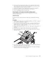
Reconnect the LCD display panel cable to the LCD display panel.
4.
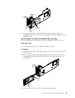
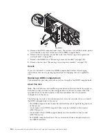
Reinstall the front operator panel
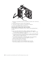
Release
latch
LCD/Operator
panel
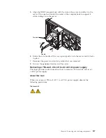
5.
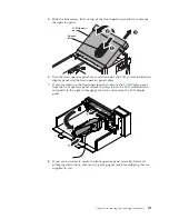
Reconnect the front operator panel cable to the storage book board.
6.
Reinstall the storage book in the server.
7.
Reconnect the power cords and any cables that you removed.
8.
Turn on the peripheral devices and the server.
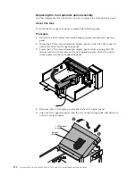
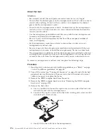
Removing and replacing FRUs
This topic provides information about removing and replacing FRUs.
FRUs must be replaced or installed only by trained service technicians.
The illustrations in this document might differ slightly from the hardware.
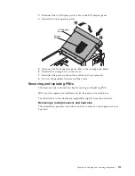
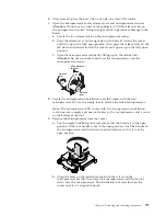
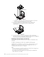
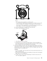
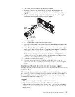
Removing a microprocessor and heat sink
This information provides instructions on how to remove a microprocessor and
heat sink.
Chapter 6. Removing and replacing components
275
Summary of Contents for X3850 X6
Page 1: ...System x3850 X6 and x3950 X6 Types 3837 and 3839 Installation and Service Guide...
Page 2: ......
Page 3: ...System x3850 X6 and x3950 X6 Types 3837 and 3839 Installation and Service Guide...
Page 138: ...120 System x3850 X6 and x3950 X6 Types 3837 and 3839 Installation and Service Guide...
Page 225: ...25 26 27 Chapter 5 Parts listing System x3850 X6 and x3950 X6 Types 3837 and 3839 207...
Page 1682: ...1664 System x3850 X6 and x3950 X6 Types 3837 and 3839 Installation and Service Guide...
Page 1706: ...1688 System x3850 X6 and x3950 X6 Types 3837 and 3839 Installation and Service Guide...
Page 1710: ...1692 System x3850 X6 and x3950 X6 Types 3837 and 3839 Installation and Service Guide...
Page 1728: ...1710 System x3850 X6 and x3950 X6 Types 3837 and 3839 Installation and Service Guide...
Page 1729: ......
Page 1730: ...Part Number 00FH434 Printed in USA 1P P N 00FH434...