


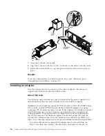


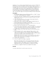
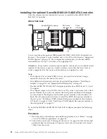

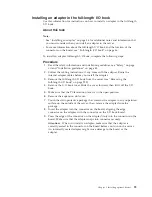

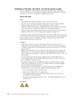

Installing the optional ServeRAID M5120 SAS/SATA Controller
User this information for instructions on how to install the ServeRAID M5120
SAS/SATA Controller.
About this task
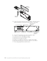
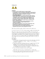
RAID cache
card connector
Release
tab
Cache
card bracket
ServeRAID M5120 adapter
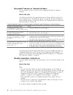
You can purchase the optional IBM ServeRAID M5120 SAS/SATA Controller for
System x. This adapter can be installed only in the PCIe slots listed in “Supported
RAID adapters” on page 87. For configuration information, see the ServeRAID
documentation at http://www.ibm.com/supportportal/.
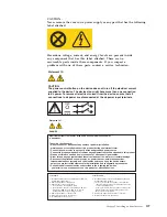
Attention:
Some cluster solutions require specific code levels or coordinated code
updates. If the device is part of a cluster solution, verify that the latest level of
code is supported for the cluster solution before you update the code.
Note:
v
This adapter is for external RAID and can be used when external storage
expansion units are attached to the server.
v
For additional information and notes about installing adapters “Installing an
adapter” on page 84 and “Supported RAID adapters” on page 87.
v
The ServeRAID M5120 SAS/SATA adapter provides base RAID levels 0, 1, and
10 support.
v
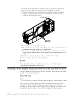
This adapter comes with a RAID cache card. The cache card comes with a flash
power module. If you want to connect the flash power module to this adapter
you must install the adapter and the falsh power module in the standard I/O
book. For information about where to install the RAID flash power module in
the server, see “Installing a RAID adapter flash power module in the standard
I/O book” on page 102 and “Installing a RAID adapter flash power module in
the storage book” on page 101.
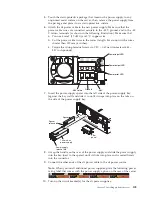
To install the IBM ServeRAID M5120 SAS/SATA adapter, complete the following
steps:
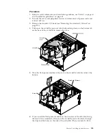
Procedure
1.
Read the safety information and installation guidelines, see “Safety” on page
vii and “Installation guidelines” on page 45.
2.
Turn off the server (see “Turning off the server” on page 41) and all attached
peripheral devices. Disconnect all power cords; then, disconnect all external
cables from the server.
94
System x3850 X6 and x3950 X6 Types 3837 and 3839: Installation and Service Guide
Summary of Contents for X3850 X6
Page 1: ...System x3850 X6 and x3950 X6 Types 3837 and 3839 Installation and Service Guide...
Page 2: ......
Page 3: ...System x3850 X6 and x3950 X6 Types 3837 and 3839 Installation and Service Guide...
Page 138: ...120 System x3850 X6 and x3950 X6 Types 3837 and 3839 Installation and Service Guide...
Page 225: ...25 26 27 Chapter 5 Parts listing System x3850 X6 and x3950 X6 Types 3837 and 3839 207...
Page 1682: ...1664 System x3850 X6 and x3950 X6 Types 3837 and 3839 Installation and Service Guide...
Page 1706: ...1688 System x3850 X6 and x3950 X6 Types 3837 and 3839 Installation and Service Guide...
Page 1710: ...1692 System x3850 X6 and x3950 X6 Types 3837 and 3839 Installation and Service Guide...
Page 1728: ...1710 System x3850 X6 and x3950 X6 Types 3837 and 3839 Installation and Service Guide...
Page 1729: ......
Page 1730: ...Part Number 00FH434 Printed in USA 1P P N 00FH434...