background image

v


Support


for


the


optional


IBM


Remote


Supervisor


Adapter


II


SlimLine


v


Key-lock


support


for


physical


security


v


Memory


change


messages


posted


to


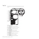
the


error


log


v


Mini-baseboard


management


controller


(mini-BMC)


(service


processor)


v


Power


management


v


Power-on


self-test


(POST)


v


Read-only


memory


(ROM)


checksums


v


Redundant


Ethernet


capabilities


(requires


an


optional


Ethernet


adapter)


with


failover


support


v


Simple-swap


Serial


Advanced


Technology


Attachment


(SATA)


hard


disk


drives


(some


models)


v


Standby


voltage


for


system-management


features


and


monitoring


v


System


auto-configuring


from


the


configuration


menu


v


System-error


LED


on


the


front


bezel


and


diagnostic


LEDs


on


the


system


board


v


Upgradeable


mini-BMC


firmware


v


Upgradeable


microcode


for


POST,


basic


input/output


system


(BIOS)


code,


and


read-only


memory


(ROM)


resident


code,


locally


or


over


a


LAN


v


Vital


product


data


(VPD);


includes


serial-number


information


and


replacement


part


numbers,


stored


in


nonvolatile


memory,


for


easier


remote


maintenance


v


Wake


on


LAN

®


capability

IBM


Director


With


IBM


Director,


a


network


administrator


can


perform


the


following


tasks:


v


View


the


hardware


configuration


of


remote


systems,


in


detail


v


Monitor


the


usage


and


performance


of


critical


components,


such


as


microprocessors,


disks,


and


memory


v


Centrally


manage


individual


or


large


groups


of


IBM


and


non-IBM


Intel-processor-based


servers,


desktop


computers,


workstations,


and


mobile


computers


on


a


variety


of


platforms

IBM


Director


provides


a


comprehensive


entry-level


workgroup


hardware


manager.


It


includes


the


following


key


features:


v


Advanced


self-management


capabilities


for


maximum


system


availability.


v


Multiple


Windows


Server


2003


operating-system


platform


support,


including


Microsoft

®


Windows


2000


Server,


Windows


XP


Professional,


AIX,


i5/os,


Red


Hat


Linux

®

,


SUSE


,


VMware,


and


Novell


NetWare.


For


a


complete


list


of


operating


systems


that


support


IBM


Director,


see


the


IBM


Director


Compatibility


Document.


This


document


is


in


Portable


Document


Format


(PDF)


at


http://www.ibm.com/pc/

support/site.wss/document.do?lndocid=MIGR-61788.


It


is


updated


every


6


to


8


weeks.


v


Support


for


IBM


and


non-IBM


servers,


desktop


computers,


workstations,


and


notebook


computers.


v


Support


for


systems-management


industry


standards.


v


Integration


into


leading


workgroup


and


enterprise


systems-management


environments.


v


Ease


of


use,


training,


and


setup.

IBM


Director


also


provides


an


extensible


platform


that


supports


advanced


server


tools


that


are


designed


to


reduce


the


total


cost


of


managing


and


supporting


6


System


x3200


Types


4362


and


4363:


User’s


Guide

Summary of Contents for System x3200 4362

Page 1: ...System x3200 Types 4362 and 4363 User s Guide...

Page 2: ......

Page 3: ...System x3200 Types 4362 and 4363 User s Guide...

Page 4: ...and the Warranty and Support Information document on the IBM System x Documentation CD First Edition October 2006 Copyright International Business Machines Corporation 2006 All rights reserved US Gove...

Page 5: ...oving the two piece bezel 22 Installing a memory module 24 Installing a drive 27 Installing a CD or DVD drive 28 Installing a tape drive 30 Installing a hot swap SAS or hot swap SATA hard disk drive 3...

Page 6: ...a RAID array of hard disk drives 55 Appendix Notices 57 Trademarks 57 Important notes 58 Product recycling and disposal 59 Battery return program 60 Electronic emission notices 61 Federal Communicati...

Page 7: ...alleert eerst de veiligheidsvoorschriften Ennen kuin asennat t m n tuotteen lue turvaohjeet kohdasta Safety Information Avant d installer ce produit lisez les consignes de s curit Vor der Installation...

Page 8: ...rsions of the caution or danger statement in the IBM Safety Information book For example if a caution statement begins with a number 1 translations for that caution statement appear in the IBM Safety...

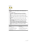
Page 9: ...quipment when there is evidence of fire water or structural damage v Disconnect the attached power cords telecommunications systems networks and modems before you open the device covers unless instruc...

Page 10: ...lithium battery replace it only with the same module type made by the same manufacturer The battery contains lithium and can explode if not properly used handled or disposed of Do not v Throw or immer...

Page 11: ...he device v Use of controls or adjustments or performance of procedures other than those specified herein might result in hazardous radiation exposure DANGER Some laser products contain an embedded Cl...

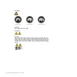
Page 12: ...n on the device and the power switch on the power supply do not turn off the electrical current supplied to the device The device also might have more than one power cord To remove all electrical curr...

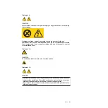
Page 13: ...ect a problem with one of these parts contact a service technician Statement 12 CAUTION The following label indicates a hot surface nearby Statement 13 DANGER Overloading a branch circuit is potential...

Page 14: ...Statement 15 CAUTION Make sure that the rack is secured properly to avoid tipping when the server unit is extended xii System x3200 Types 4362 and 4363 User s Guide...

Page 15: ...basic instructions for installing some optional devices v Warranty and Support Information This document is in Portable Document Format PDF on the IBM System x Documentation CD It contains information...

Page 16: ...ety Information document which is on the IBM System x Documentation CD Each statement is numbered for reference to the corresponding statement in the Safety Information document The following notices...

Page 17: ...ller v One internal SAS port mini PCI slot v Six Universal Serial Bus USB v2 0 ports two on front and four on rear v Keyboard port v Mouse port v ATA 100 single channel IDE controller bus mastering v...

Page 18: ...on CD on page 51 v Integrated network support The server comes with an integrated Broadcom NetXtreme Gigabit Ethernet controller which supports connection to a 10 Mbps 100 Mbps or 1000 Mbps network Fo...

Page 19: ...63 v Advanced Configuration and Power Interface ACPI v Advanced Desktop Management Interface DMI features v Automatic BIOS recovery to a backup image v Automatic error retry or recovery v Automatic me...

Page 20: ...itor the usage and performance of critical components such as microprocessors disks and memory v Centrally manage individual or large groups of IBM and non IBM Intel processor based servers desktop co...

Page 21: ...systems_management which presents an overview of IBM Systems Management and IBM Director Update Xpress program The UpdateXpress program is available for most System x3200 servers and optional devices...

Page 22: ...the system is turned off and the power cord is still attached to the server Note If this LED is off it does not mean that there is no electrical power in the server The LED might be burned out To remo...

Page 23: ...disk drive is in use When the drive is removed this LED also is visible on the hard disk drive backplane next to the drive connector The backplane is the printed circuit board behind drive bays 4 thr...

Page 24: ...ctor Connect the power cord to this connector Serial 2 connector Connect a 9 pin serial device to this connector Mouse connector Connect a mouse device to this connector Keyboard connector Connect a k...

Page 25: ...server can respond to remote requests to turn on the server Turning on the server Approximately 20 seconds after the server is connected to ac power the power control button becomes active and you ca...

Page 26: ...can be turned off in any of the following ways v You can turn off the server from the operating system if your operating system supports this feature After an orderly shutdown of the operating system...

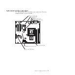
Page 27: ...el The illustrations in this document might differ slightly from your hardware Front adapter support bracket Drive cage EMC shields Filler panels Cover System board Upper bezel Lower bezel Microproces...

Page 28: ...pin Drive connector optional Hard disk drive fan connector Hard disk drive backplane connector Microprocessor connector DIMM 1 connector DIMM 2 connector DIMM 3 connector DIMM 4 connector Front panel...

Page 29: ...system board There are no changeable switches on the system board NMI button NMI button switch SW1 Serial 2 switch JP9 System rest nopop JP3 Boot block jumper JP6 Clear CMOS jumper JP 2 mini BMC force...

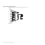
Page 30: ...illustration shows the external input output I O connectors on the system board Mouse Keyboard Serial 1 Parallel Video USB 2 USB 2 Ethernet Remote Supervisor Adapter II SlimLine Ethernet Serial 2 16...

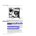
Page 31: ...d and connectors for user installable options DIMM 4 DIMM 3 DIMM 2 DIMM 1 Slot 4 PCI 32 bit 33 MHz Slot 5 PCI 32 bit 33 MHz Slot 3 PCI 32 bit 33 MHz Slot 2 PCI Express x8 Slot 1 PCI Express x1 Remote...

Page 32: ...y known issues are addressed and that your server is ready to function at maximum levels of performance To download firmware updates for your server go to http www ibm com servers eserver support xser...

Page 33: ...emoving and installing a specific hot swap component for any additional procedures that you might have to perform before you remove or install the component v When you have to access the inside of the...

Page 34: ...other electronic devices To avoid damage keep static sensitive devices in their static protective packages until you are ready to install them To reduce the possibility of electrostatic discharge obse...

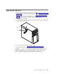
Page 35: ...r on its side 4 Unlock the side cover then press the cover release latch down as indicated by the two arrows on the latch Cover release latch Key lock 5 Lift the side cover off the server and set it a...

Page 36: ...you do not have to remove the side cover However the side cover must be unlocked To remove the two piece bezel complete the following steps 1 Unlock the side cover 2 Remove the side cover see Removing...

Page 37: ...chassis then rotate the upper bezel to the right side of the server to disengage the two right side tabs from the chassis Set the upper bezel aside For instructions for replacing the two piece bezel s...

Page 38: ...m and select System Summary from the menu For additional information see Chapter 3 Configuring the server on page 47 v For two way memory interleaving DIMMs must be installed in matched pairs If one D...

Page 39: ...to stop which could result in the loss of data To avoid this potential problem always use an electrostatic discharge wrist strap or other grounding system when you work inside the server with the powe...

Page 40: ...e on the server Then remove the new DIMM from the package 7 Turn the DIMM so that the DIMM keys align correctly with the slot 8 Insert the DIMM into the connector by aligning the edges of the DIMM wit...

Page 41: ...g a SAS or SATA device be sure to set the SAS or SATA ID for that device v Optional external USB diskette drives tape drives CD drives CD RW drives DVD CD RW combo and multiburner drives are examples...

Page 42: ...nstallation guidelines on page 18 2 Turn off the server and peripheral devices and disconnect the power cords and all external cables 3 Remove the side cover see Removing the side cover on page 21 4 R...

Page 43: ...nstruments and avoid direct exposure to the beam Class 1 Laser Product Laser Klasse 1 Laser Klass 1 Luokan 1 Laserlaite Appareil A Laser de Classe 1 6 Touch the static protective package that contains...

Page 44: ...dual inline memory modules DIMMs 12 If you have another drive to install or remove do so now 13 Connect the power cable to the rear of the drive The connectors are keyed and can be inserted only one w...

Page 45: ...y If you have other devices to install or remove do so now otherwise go to Completing the installation on page 42 Installing a hot swap SAS or hot swap SATA hard disk drive Some server models come wit...

Page 46: ...ently slide the drive assembly into the drive bay until the drive stops d Push the drive tray handle to the closed locked position e Check the hard disk drive status indicator to make sure that the ha...

Page 47: ...drives and backplane are connected to channel A Device ID Drive bay 4 0 Drive bay 5 1 Drive bay 6 2 Drive bay 7 3 Installing a simple swap SATA hard disk drive Some server models come with simple swa...

Page 48: ...nd place it on a static protective surface 6 Align the drive assembly with the guide rails in the bay the connector end of the drive goes in first 7 Pull the loops of the drive assembly toward each ot...

Page 49: ...with SATA drives but do not use both at the same time use one or the other v Signal cables Signal cables are typically flat cables also called ribbon cables that connect parallel IDE SATA SAS and disk...

Page 50: ...d only in its dedicated connector on the system board See System board internal connectors on page 14 for the location of the connector For additional information see the documentation that comes with...

Page 51: ...ome with the adapter Route the adapter cables before you install the adapter 4 Follow the instructions that come with the adapter to set jumpers or switches if any 5 Rotate the rear adapter retention...

Page 52: ...tall an expansion slot screw at the rear of the adapter 11 If you are installing a full length adapter press on the release lever on the right side of the front adapter retention bracket to release th...

Page 53: ...ower supplies If the server contains a non hot swap power supply that requires replacement the power supply must be replaced by a service technician When you remove or install a hot swap power supply...

Page 54: ...etal surface on the server then remove the power supply from the package and place it on a static protective surface 8 Place the power supply into the bay guides 9 Press down on the orange release lev...

Page 55: ...d nuts that fit the rope clip v A security cable v A lock such as a combination lock or padlock Rope clip To install a rope clip complete the following steps 1 Turn off the server and all attached dev...

Page 56: ...t all the cables and for some devices run the Configuration Setup Utility program Follow the instructions in this section Reinstalling the two piece bezel To reinstall the two piece bezel complete the...

Page 57: ...ssis a Insert the two bottom tabs on the lower bezel into the matching holes in the front of the chassis b Tilt the top of the lower bezel into position on the chassis until the lower bezel locks secu...

Page 58: ...sure that all cables adapters and other components are installed and seated correctly and that you have not left loose tools or parts inside the server Also make sure that all internal cables are corr...

Page 59: ...Supervisor Adapter II SlimLine Ethernet Serial 2 Fixed power supply Hot swap power supplies AC power LED DC power LED Updating the server configuration When you start the server for the first time af...

Page 60: ...18 and the documentation that comes with the device 2 Turn off the server and all attached devices 3 Follow the instructions that come with the device to prepare it for installation and to connect it...

Page 61: ...The Broadcom NetXtreme Gigabit Ethernet Boot Agent is part of the BIOS You can use it to configure the network as a startable device and you can customize where the network Startup optional devices oc...

Page 62: ...ary Select this choice to view the processor information including the type speed and cache size of the microprocessor v System Information Select this choice to view information about the server When...

Page 63: ...te and time in the server in 24 hour format hour minute second This choice is on the Configuration Setup Utility menu only v System Security Select this choice to set password settings See Using passw...

Page 64: ...em event log LAN settings and to enable or disable the clear system event log and BIOS POST watchdog Disable is the default setting for clearing the system event log and BIOS POST watchdog View System...

Page 65: ...ing the ServerGuide Setup and Installation CD The ServerGuide Setup and Installation CD contains a setup and installation program that is designed for your server The ServerGuide program detects the s...

Page 66: ...use the CD to configure any supported IBM server model The setup program provides a list of tasks that are required to set up the server model On a server with a ServeRAID adapter or integrated SAS SA...

Page 67: ...ions for your operating system Using the Boot Menu program The Boot Menu program is a built in menu driven configuration utility program that you can use to temporarily redefine the first startup devi...

Page 68: ...Click the Install and use tab 4 Click Product documentation LSI Configuration Utility program Use the LSI Configuration Utility program to configure and manage redundant array of independent disks RAI...

Page 69: ...inistrator password you are prompted to type the password 3 To select a controller channel from the list of adapters use the arrow keys and press Enter 4 To change the settings of the selected items f...

Page 70: ...the arrow keys to highlight the first drive in the pair then press the Minus or Plus key to change the mirror value to Primary 5 Continue to select the next drive using the Minus or Plus key until yo...

Page 71: ...TO THE IMPLIED WARRANTIES OF NON inFRINGEMENT MERCHANTABILITY OR FITNESS FOR A PARTICULAR PURPOSE Some states do not allow disclaimer of express or implied warranties in certain transactions therefore...

Page 72: ...in the United States and other countries Other company product or service names may be trademarks or service marks of others Important notes Processor speeds indicate the internal clock speed of the m...

Page 73: ...e found on IBM s Internet site at http www ibm com ibm environment products prp shtml Esta unidad debe reciclarse o desecharse de acuerdo con lo establecido en la normativa nacional o local aplicable...

Page 74: ...potential effects of EEE on the environment and human health due to the potential presence of hazardous substances in EEE For proper collection and treatment contact your local IBM representative Bat...

Page 75: ...nsible for any radio or television interference caused by using other than recommended cables and connectors or by unauthorized changes or modifications to this equipment Unauthorized changes or modif...

Page 76: ...22 European Standard EN 55022 The limits for Class A equipment were derived for commercial and industrial environments to provide reasonable protection against interference with licensed communication...

Page 77: ...configuration programs Boot Menu 47 configuration programs continued Broadcom NetXtreme Gigabit Ethernet Boot Agent 47 Broadcom NetXtreme Gigabit Ethernet controller 47 Configuration Setup Utility pr...

Page 78: ...hard disk drive bay 13 removable media drive bay 13 28 removing 28 31 SAS 13 SATA 13 firmware update 7 formatting hard disk drive 55 H handling static sensitive devices 20 hard disk drive activity LED...

Page 79: ...2 O online publications 2 optional device installation guidelines 18 optional device continued static sensitive 20 optional devices connectors 10 options adapters 36 37 connectors 17 drives 27 instal...

Page 80: ...ion 52 Setup and Installation CD 47 starting the Setup and Installation CD 52 using 51 serviceability features 5 setup advanced 50 with ServerGuide 52 simple swap drives 33 size 3 specifications 3 sta...

Page 81: ...Web site continued Update Xpress program 7 weight 3 Index 67...

Page 82: ...68 System x3200 Types 4362 and 4363 User s Guide...

Page 83: ......

Page 84: ...Part Number 42D2453 Printed in USA 1P P N 42D2453...

Reviews: