background image

v

One PCI riser-card assembly in PCI riser connector 1

The following table describes the problems that are indicated by various
combinations of the power-supply LEDs on an AC power supply and suggested
actions to correct the detected problems.

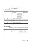
AC power-supply LEDs

Description

Action

Notes

AC

DC

Error (!)

On

On

Off

Normal operation.

Off

Off

Off

No ac power to the
server or a problem
with the ac power
source.

1. Check the ac power to the

server.

2. Make sure that the power

cord is connected to a
functioning power source.

3. Restart the server. If the error

remains, check the
power-supply LEDs.

4. If the problem remains,

replace the power-supply.

This is a normal
condition when no ac
power is present.

Off

Off

On

The power supply
has failed.

Replace the power supply.

Off

On

Off

The power supply
has failed.

Replace the power supply.

Off

On

On

The power supply
has failed.

Replace the power supply.

On

Off

On

The power supply
has failed.

Replace the power supply.

On

On

On

The power supply
has failed.

Replace the power supply.

System pulse LEDs

The following LEDs are on the system board and monitor the system power-on and
power-off sequencing and boot progress:

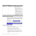
Table 4. System pulse LEDs

LED

Description

Action

RTMM heartbeat

Power-on and power-off
sequencing.

1. If the LED blinks at 1Hz, it is functioning

properly and no action is necessary.

2. If the LED is not blinking, (trained service

technician only) replace the system board.

Chapter 3. Diagnostics

189

Summary of Contents for System x iDataPlex dx360 M4 7912

Page 1: ...System x iDataPlex dx360 M4 Types 7912 and 7913 Problem Determination and Service Guide...

Page 2: ......

Page 3: ...System x iDataPlex dx360 M4 Types 7912 and 7913 Problem Determination and Service Guide...

Page 4: ...ices and User Guide documents on the IBM Documentation CD and the Warranty Information document The most recent version of this document is available at http www ibm com supportportal Fifth Edition Se...

Page 5: ...6 Viewing event logs from the Setup utility 16 Viewing event logs without restarting the server 17 Clearing the error logs 18 POST 18 POST UEFI diagnostic codes 19 System event log 30 Integrated manag...

Page 6: ...ard tray in a 2U chassis 279 Removing the system board tray cover 280 Installing the system board tray cover 280 Removing a GPGPU enclosure 281 Installing a GPGPU enclosure 282 Removing the 2U chassis...

Page 7: ...the server 342 Using the ServerGuide Setup and Installation CD 343 Using the Setup utility 345 Using the Boot Manager program 350 Starting the backup server firmware 351 Using the integrated managemen...

Page 8: ...372 Japan Electronics and Information Technology Industries Association JEITA statement 372 Korea Communications Commission KCC statement 372 Russia Electromagnetic Interference EMI Class A statement...

Page 9: ...ety Information Avant d installer ce produit lisez les consignes de s curit Vor der Installation dieses Produkts die Sicherheitshinweise lesen Prima di installare questo prodotto leggere le Informazio...

Page 10: ...at they present v Electrical hazards especially primary power Primary voltage on the frame can cause serious or fatal electrical shock v Explosive hazards such as a damaged CRT face or a bulging capac...

Page 11: ...r electrical outlet so that you can turn off the power quickly in the event of an electrical accident v Disconnect all power before you perform a mechanical inspection work near power supplies or remo...

Page 12: ...nt is labeled Statement 1 translations for that caution statement are in the Safety Information document under Statement 1 Be sure to read all caution and danger statements in this document before you...

Page 13: ...quipment when there is evidence of fire water or structural damage v Disconnect the attached power cords telecommunications systems networks and modems before you open the device covers unless instruc...

Page 14: ...ace it only with the same module type made by the same manufacturer The battery contains lithium and can explode if not properly used handled or disposed of Do not v Throw or immerse into water v Heat...

Page 15: ...e device v Use of controls or adjustments or performance of procedures other than those specified herein might result in hazardous radiation exposure DANGER Some laser products contain an embedded Cla...

Page 16: ...pplied to the device The device also might have more than one power cord To remove all electrical current from the device ensure that all power cords are disconnected from the power source 1 2 Stateme...

Page 17: ...inside these components If you suspect a problem with one of these parts contact a service technician Statement 12 CAUTION The following label indicates a hot surface nearby Statement 26 CAUTION Do n...

Page 18: ...CAUTION Hazardous moving parts are nearby xvi System x iDataPlex dx360 M4 Types 7912 and 7913 Problem Determination and Service Guide...

Page 19: ...agnostics on page 187 for information about using light path diagnostics LEDs v Event logs See System event log on page 30 for information about notification events and diagnosis v Software or operati...

Page 20: ...orrect configuration If the server is incorrectly configured a system function can fail to work when you enable it if you make an incorrect change to the server configuration a system function that ha...

Page 21: ...for assistance with additional problem determination and possible hardware replacement To open an online service request go to the http www ibm com support entry portal Open_service_request call for s...

Page 22: ...4 System x iDataPlex dx360 M4 Types 7912 and 7913 Problem Determination and Service Guide...

Page 23: ...BM Warranty Information This printed document contains the warranty terms and a pointer to the IBM Statement of Limited Warranty on the IBM website v User s Guide This document is in Portable Document...

Page 24: ...n document The following notices and statements are used in this document v Note These notices provide important tips guidance or advice v Important These notices provide information or advice that mi...

Page 25: ...itude 0 to 950 m 0 to 3116 ft Derate maximum temperature by 1 C for every 175 m 574 ft increase in elevation to a maximum of 3050 m 10004 ft at an ambient temperature of 5 C to 28 C 41 F to 82 F Notes...

Page 26: ...output vary depending on the number and type of optional features installed and the power management optional features in use 2 The noise emission level stated is the declared upper limit sound power...

Page 27: ...ver can be used simultaneously Note The maximum video resolution is 1600 x 1200 at 75 Hz v Systems management Ethernet connector Use this connector to connect the server to a network for full systems...

Page 28: ...slowly and one or more fans might start running to provide cooling while the system board tray is connected to power You can turn on the system board tray by pressing the power control button The serv...

Page 29: ...t have more than one power cord To remove all electrical current from the device ensure that all power cords are disconnected from the power source 1 2 The system board tray can be turned off in any o...

Page 30: ...The following illustration shows the internal connectors on the system board DIMM 4 1 DIMM 16 13 DIMM 12 5 Microprocessor 1 Internal USB Microprocessor 2 Network adapter connector Battery Front panel...

Page 31: ...3 Clears the real time clock RTC registry JP3 UEFI boot backup jumper v Pins 1 and 2 Normal default Loads the primary server firmware ROM page v Pins 2 and 3 Loads the secondary backup server firmware...

Page 32: ...LED Microprocessor 2 error LED Battery error LED Riser 1 error LED Mezz card error LED RTMM heartbeat error LED IMM heartbeat error LED Riser 2 error LED DIMM 12 5 error LEDs Power LED Light Path Powe...

Page 33: ...nfiguration Vital product data firmware and UEFI configuration Hard disk drive health RAID controller configuration Controller and service processor event logs including the following information Syst...

Page 34: ...l system status messages from the service processor You can view the contents of the system event log from the Setup utility The system event log is limited in size When it is full new entries will no...

Page 35: ...ion of IPMItool For an overview of IPMI go to http www ibm com developerworks linux blueprints and click Using Intelligent Platform Management Interface IPMI on IBM Linux platforms You can view the IM...

Page 36: ...tically cleared each time the server is restarted 1 Turn on the server 2 When the prompt F1 Setup is displayed press F1 If you have set both a power on password and an administrator password you must...

Page 37: ...rt site for an applicable service bulletin that applies to this Processor error 3 Trained Service technician only Replace Processor Inspect Processor socket and replace the system board first if socke...

Page 38: ...ce technician only Replace the Processor Inspect Processor socket and replace the system board first if socket is damaged I 1800B I 1800B A cache size mismatch has been detected for one or more proces...

Page 39: ...onstraints The Vendor ID for the device is and the Device ID is Explanation OUT_OF_RESOURCES PCI Option ROM Severity Info User response Complete the following steps 1 If this PCIe device and or any at...

Page 40: ...cessful Trained service technician only Replace the system board I 3818003 I 3818003 The CRTM flash driver could not lock the secure flash region Explanation CRTM Could not lock secure flash region Se...

Page 41: ...adapter replace that card 4 Trained Service technician only Replace the processor S 2018001 S 2018001 An Uncorrected PCIe Error has Occurred at Bus Device Function The Vendor ID for the device is and...

Page 42: ...id not intentionally trigger the reboots check logs for probable cause 3 Undo recent system changes settings or devices added If not recent system changes remove all options then remove CMOS battery f...

Page 43: ...Log may contain a recent 00580A4 event denoting detected change in DIMM population that could be related to this problem 2 If no problem is observed on the DIMM connectors or the problem persists repl...

Page 44: ...ted Procesor to another Processor socket and retry If problem follows the affected Processor or there is only one Processor replace the affected Processor 8 Trained Service technician only Replace the...

Page 45: ...in or firmware update that applies to this error 4 Trained Service technician only Replace the system board W 3058009 W 3058009 DRIVER HEALTH PROTOCOL Missing Configuraiton Requires Change Settings Fr...

Page 46: ...This will reboot the entire system 4 Check IBM support site for an applicable service bulletin or firmware update that applies to this error 5 Reflash IMM Firmware 6 Remove and re install CMOS batter...

Page 47: ...to this memory error The release notes will list the known problems the update addresses 3 If the previous steps do not resolve the problem at the next maintenance opportunity replace the affected DI...

Page 48: ...when the server is started Warning Warning messages do not require immediate action they indicate possible problems such as when the recommended maximum ambient temperature is exceeded Error Error me...

Page 49: ...User response Information only no action is required 40000005 00000000 Ethernet MTU setting modified from arg1 to arg2 by user arg3 Explanation This message is for the use case where a user modifies...

Page 50: ...0010 SNMP Trap ID Automatically notify Support No User response Information only no action is required 4000000b 00000000 IP address of default gateway modified from arg1 to arg2 by user arg3 Explanat...

Page 51: ...Event No Severity Warning Alert Category System Remote Login Serviceable No CIM Information Prefix IMM and ID 0016 SNMP Trap ID 30 Automatically notify Support No User response Complete the following...

Page 52: ...efix IMM and ID 0021 SNMP Trap ID Automatically notify Support No User response Information only no action is required 40000016 00000000 ENET arg1 DHCP HSTN arg2 DN arg3 IP arg4 SN arg5 GW arg6 DNS1 a...

Page 53: ...esponse Information only no action is required 4000001c 00000000 Watchdog arg1 Screen Capture Occurred Explanation This message is for the use case where an operating system error has occurred and the...

Page 54: ...r response Update the IMM firmware to a version that the server supports Important Some cluster solutions require specific code levels or coordinated code updates If the device is part of a cluster so...

Page 55: ...ally notify Support No User response Information only no action is required 40000025 00000000 The arg1 on system arg2 is 75 full Explanation This message is for the use case where a Management Control...

Page 56: ...sword 4000002a 00000000 arg1 firmware mismatch internal to system arg2 Please attempt to flash the arg3 firmware Explanation This message is for the use case where a specific type of firmware mismatch...

Page 57: ...notify Support No User response Information only no action is required 40000031 00000000 IPv6 static IP configuration enabled by user arg1 Explanation IPv6 static address assignment method is enabled...

Page 58: ...response Information only no action is required 40000037 00000000 ENET arg1 IPv6 LinkLocal HstName arg2 IP arg3 Pref arg4 Explanation IPv6 Link Local address is active Internal Event No Severity Info...

Page 59: ...eout Serviceable No CIM Information Prefix IMM and ID 0060 SNMP Trap ID 26 Automatically notify Support No User response 1 Reconfigure the watchdog timer to a higher value 2 Make sure that the IMM Eth...

Page 60: ...ity Info Alert Category none Serviceable No CIM Information Prefix IMM and ID 0066 SNMP Trap ID Automatically notify Support No User response Information only no action is required 40000043 00000000 S...

Page 61: ...inventory to change Internal Event No Severity Info Alert Category none Serviceable No CIM Information Prefix IMM and ID 0072 SNMP Trap ID Automatically notify Support No User response Information on...

Page 62: ...xplanation A user configured the Serial Port mode Internal Event No Severity Info Alert Category none Serviceable No CIM Information Prefix IMM and ID 0078 SNMP Trap ID Automatically notify Support No...

Page 63: ...o Severity Info Alert Category none Serviceable No CIM Information Prefix IMM and ID 0084 SNMP Trap ID Automatically notify Support No User response Information only no action is required 40000055 000...

Page 64: ...Alert Category none Serviceable No CIM Information Prefix IMM and ID 0090 SNMP Trap ID Automatically notify Support No User response Information only no action is required 4000005b 00000000 Secure We...

Page 65: ...on is required 40000061 00000000 License key for arg1 removed by user arg2 Explanation A user removes a License Key Internal Event No Severity Info Alert Category none Serviceable No CIM Information P...

Page 66: ...r response Information only no action is required 40000067 00000000 User arg1 role set to arg2 Explanation A user account role assigned Internal Event No Severity Info Alert Category none Serviceable...

Page 67: ...to a file by user arg2 Explanation A user saves a Management Controller configuration to a file Internal Event No Severity Info Alert Category none Serviceable No CIM Information Prefix IMM and ID 01...

Page 68: ...response Information only no action is required 40000073 00000000 The maximum power cap value changed from arg1 watts to arg2 watts Explanation Maximum Power Cap value changed Internal Event No Severi...

Page 69: ...sponse Information only no action is required 40000079 00000000 Static Power Savings mode has been turned on by user arg1 Explanation Static Power Savings mode turned on by user Internal Event No Seve...

Page 70: ...00000000 Power cap throttling occurred Explanation Power cap throttling occurrred Internal Event No Severity Info Alert Category none Serviceable No CIM Information Prefix IMM and ID 0127 SNMP Trap ID...

Page 71: ...lease attempt to flash the FPGA firmware to the same level on all nodes Explanation A mismatch of FPGA firmware has been detected between nodes Internal Event No Severity Error Alert Category System O...

Page 72: ...rt No User response 1 Turn off the server and disconnect it from the power source You must disconnect the server from ac power to reset the IMM 2 After 45 seconds reconnect the server to the power sou...

Page 73: ...Lower Critical sensor going low has asserted Internal Event No Severity Error Alert Category Critical Fan Failure Serviceable Yes CIM Information Prefix PLAT and ID 0480 SNMP Trap ID 11 Automatically...

Page 74: ...ollowing steps until the problem is solved 1 Make sure that the fans are operating that there are no obstructions to the airflow front and rear of the server that the air baffle is in place and correc...

Page 75: ...4 Replace riser 2 card 80010701 1003ffff Numeric sensor NumericSensorElementName going high upper non critical has asserted Riser 1B Temp Explanation This message is for the use case when an implement...

Page 76: ...Server Features and specifications for more information 3 Make sure that the heat sink for mezz card installed properly 4 Replace mezz card 80010701 2d01ffff Numeric sensor NumericSensorElementName g...

Page 77: ...n replace both GPU cards 5 If you are using NVidia GPU card then replace GPU 2 card 80010901 0b03ffff Numeric sensor NumericSensorElementName going high upper critical has asserted Explanation This me...

Page 78: ...operating that there are no obstructions to the airflow front and rear of the server that the air baffle is in place and correctly installed and that the server cover is installed and completely close...

Page 79: ...perature Serviceable Yes CIM Information Prefix PLAT and ID 0494 SNMP Trap ID 0 Automatically notify Support No User response 1 Make sure that the fans are operating that there are no obstructions to...

Page 80: ...recoverable has asserted Mic 1 VR Temp Explanation This message is for the use case when an implementation has detected an Upper Non recoverable sensor going high has asserted Internal Event No Severi...

Page 81: ...ly installed and that the server cover is installed and completely closed 2 Check the ambient temperature You must be operating within the specifications see Server Features and specifications for mor...

Page 82: ...d an Upper Non recoverable sensor going high has asserted Internal Event No Severity Error Alert Category Critical Temperature Serviceable Yes CIM Information Prefix PLAT and ID 0498 SNMP Trap ID 0 Au...

Page 83: ...notify Support No User response Complete the following step to solve PCI I O resource errors 1 Go to F1 Setup 2 System Settings 3 Device and I O ports 4 PCI 64 bit Resource and choose enable 80070114...

Page 84: ...re Internal Event No Severity Error Alert Category Critical Voltage Serviceable Yes CIM Information Prefix PLAT and ID 0522 SNMP Trap ID 1 Automatically notify Support No User response 1 Check the sys...

Page 85: ...ch as bundled cables to the airflow from the power supply fan 2 Use the IBM Power Configurator utility to ensure current system power consumption is under limitation For more information and to downlo...

Page 86: ...rred trained technician only replace the system board 8007021b 0301ffff Sensor SensorElementName has transitioned to critical from a less severe state CPU 1 QPILinkErr Explanation This message is for...

Page 87: ...letely closed 2 Check the ambient temperature You must be operating within the specifications see Server Features and specifications for more information 3 Make sure that the heat sink for microproces...

Page 88: ...s solved 1 Check power supply n LED 2 Replace power supply n n power supply number 80070614 2201ffff Sensor SensorElementName has transitioned to non recoverable TPM Phy Pres Set Explanation This mess...

Page 89: ...ke sure that the connectors on fan n are not damaged 2 Make sure that the fan n connectors on the system board are not damaged 3 Make sure that the fans are correctly installed 4 Reseat the fans 5 Rep...

Page 90: ...tical CPU Serviceable Yes CIM Information Prefix PLAT and ID 0042 SNMP Trap ID 40 Automatically notify Support No User response 1 Update the latest level of system firmware and device drivers are inst...

Page 91: ...ally notify Support No User response No action information only 806f000f 220101ff The System ComputerSystemElementName has detected no memory in the system ABR Status Explanation This message is for t...

Page 92: ...re ABR Status Explanation This message is for the use case when an implementation has detected that System Firmware Error Unrecoverable Keyboard failure has occurred Internal Event No Severity Error A...

Page 93: ...Status 806f000f 2201ffff The System ComputerSystemElementName encountered a POST Error ABR Status Explanation This message is for the use case when an implementation has detected a Post Error Internal...

Page 94: ...and adapter firmware Important Some cluster solutions require specific code levels or coordinated code updates If the device is part of a cluster solution verify that the latest level of code is supp...

Page 95: ...apters 5 Replace the riser card 6 Trained service technicians only Replace the system board 806f0021 3004ffff Fault in slot PhysicalConnectorSystemElementName on system ComputerSystemElementName PCI 4...

Page 96: ...Info Alert Category System Other Serviceable No CIM Information Prefix PLAT and ID 0368 SNMP Trap ID Automatically notify Support No User response No action information only 806f0025 2c01ffff ManagedE...

Page 97: ...his message is for the use case when an implementation has detected a Power Supply has failed Internal Event No Severity Error Alert Category Critical Power Serviceable Yes CIM Information Prefix PLAT...

Page 98: ...Internal Event No Severity Error Alert Category Critical Memory Serviceable Yes CIM Information Prefix PLAT and ID 0138 SNMP Trap ID 41 Automatically notify Support Yes User response 1 Check the IBM...

Page 99: ...Trained technician only Remove the affected microprocessor and check the microprocessor socket pins for any damaged pins If a damage is found replace the system board 6 Trained technician only Replac...

Page 100: ...Internal Event No Severity Error Alert Category Critical Memory Serviceable Yes CIM Information Prefix PLAT and ID 0138 SNMP Trap ID 41 Automatically notify Support Yes User response 1 Check the IBM...

Page 101: ...Trained technician only Remove the affected microprocessor and check the microprocessor socket pins for any damaged pins If a damage is found replace the system board 6 Trained technician only Replace...

Page 102: ...Internal Event No Severity Error Alert Category Critical Memory Serviceable Yes CIM Information Prefix PLAT and ID 0138 SNMP Trap ID 41 Automatically notify Support Yes User response 1 Check the IBM...

Page 103: ...Trained technician only Remove the affected microprocessor and check the microprocessor socket pins for any damaged pins If a damage is found replace the system board 6 Trained technician only Replac...

Page 104: ...correctable error Internal Event No Severity Error Alert Category Critical Memory Serviceable Yes CIM Information Prefix PLAT and ID 0138 SNMP Trap ID 41 Automatically notify Support Yes User response...

Page 105: ...ician only Reseat the microprocessor and then restart the server 2 Trained technician only Replace microprocessor n n microprocessor number 806f0123 2101ffff Reboot of system ComputerSystemElementName...

Page 106: ...quire specific code levels or coordinated code updates If the device is part of a cluster solution verify that the latest level of code is supported for the cluster solution before you update the code...

Page 107: ...n an implementation has detected a Memory Scrub failure Internal Event No Severity Error Alert Category Critical Memory Serviceable Yes CIM Information Prefix PLAT and ID 0136 SNMP Trap ID 41 Automati...

Page 108: ...ogs to a different memory channel or microprocessor 4 If the problem follows the DIMM replace the failing DIMM 5 Trained technician only If the problem occurs on the same DIMM connector check the DIMM...

Page 109: ...atically notify Support No User response Note Each time you install or remove a DIMM you must disconnect the server from the power source then wait 10 seconds before restarting the server 1 Check the...

Page 110: ...ins If a damage is found replace the system board 7 Trained technician only Replace the affected microprocessor 806f030c 2009ffff Scrub Failure for PhysicalMemoryElementName on Subsystem MemoryElement...

Page 111: ...n the system board or the event logs to a different memory channel or microprocessor 4 If the problem follows the DIMM replace the failing DIMM 5 Trained technician only If the problem occurs on the s...

Page 112: ...esponse Note Each time you install or remove a DIMM you must disconnect the server from the power source then wait 10 seconds before restarting the server 1 Check the IBM support website for an applic...

Page 113: ...roprocessor socket pins for any damaged pins If a damage is found replace the system board 7 Trained technician only Replace the affected microprocessor 806f030c 2581ffff Scrub Failure for PhysicalMem...

Page 114: ...tomatically notify Support No User response 1 Make sure the DIMM is installed correctly 2 If the DIMM was disabled because of a memory fault memory uncorrectable error or memory logging limit reached...

Page 115: ...update that applies to this memory event If no memory fault is recorded in the logs and no DIMM connector error LED is lit you can re enable the DIMM through the Setup utility or the Advanced Settings...

Page 116: ...because of a memory fault memory uncorrectable error or memory logging limit reached follow the suggested actions for that error event and restart the server 3 Check the IBM support website for an app...

Page 117: ...tegory System Other Serviceable No CIM Information Prefix PLAT and ID 0131 SNMP Trap ID Automatically notify Support No User response 1 Make sure the DIMM is installed correctly 2 If the DIMM was disa...

Page 118: ...his message is for the use case when an implementation has detected that Memory has been Disabled Internal Event No Severity Info Alert Category System Other Serviceable No CIM Information Prefix PLAT...

Page 119: ...ace microprocessor n n microprocessor number 806f0507 0302ffff ProcessorElementName has a Configuration Mismatch CPU 2 Explanation This message is for the use case when an implementation has detected...

Page 120: ...e affected DIMMs as indicated by the error LEDs on the system board or the event logs to a different memory channel or microprocessor 3 If the problem follows the DIMM replace the failing DIMM 4 Train...

Page 121: ...If the server firmware version is UEFI v1 10 or newer disconnect and reconnect the server to the power source and restart the server 8 Trained Service technician only Replace the affected microproces...

Page 122: ...d DIMMs as indicated by the error LEDs on the system board or the event logs to a different memory channel or microprocessor 3 If the problem follows the DIMM replace the failing DIMM 4 Trained techni...

Page 123: ...If the server firmware version is UEFI v1 10 or newer disconnect and reconnect the server to the power source and restart the server 8 Trained Service technician only Replace the affected microprocess...

Page 124: ...d DIMMs as indicated by the error LEDs on the system board or the event logs to a different memory channel or microprocessor 3 If the problem follows the DIMM replace the failing DIMM 4 Trained techni...

Page 125: ...If the server firmware version is UEFI v1 10 or newer disconnect and reconnect the server to the power source and restart the server 8 Trained Service technician only Replace the affected microprocess...

Page 126: ...an applicable retain tip or firmware update that applies to this memory error 2 Swap the affected DIMMs as indicated by the error LEDs on the system board or the event logs to a different memory chan...

Page 127: ...or Alert Category Critical CPU Serviceable Yes CIM Information Prefix PLAT and ID 0816 SNMP Trap ID 40 Automatically notify Support No User response 1 Update the latest level of system firmware and de...

Page 128: ...sponse 1 Make sure that the power supplies installed are with the same rating or wattage 2 Reinstall the power supplies with the same rating or wattage 806f070c 2001ffff Configuration Error for Physic...

Page 129: ...e memory population chart in the system publication 806f070c 2006ffff Configuration Error for PhysicalMemoryElementName on Subsystem MemoryElementName DIMM 6 Explanation This message is for the use ca...

Page 130: ...e on Subsystem MemoryElementName DIMM 11 Explanation This message is for the use case when an implementation has detected a Memory DIMM configuration error has been corrected Internal Event No Severit...

Page 131: ...anation This message is for the use case when an implementation has detected a Memory DIMM configuration error has been corrected Internal Event No Severity Error Alert Category Critical Memory Servic...

Page 132: ...6f0807 2584ffff ProcessorElementName has been Disabled All CPUs Explanation This message is for the use case when an implementation has detected a Processor has been Disabled Internal Event No Severit...

Page 133: ...processor and heat sink 3 Check for a server firmware update Important Some cluster solutions require specific code levels or coordinated code updates If the device is part of a cluster solution verif...

Page 134: ...umber 806f090c 2005ffff PhysicalMemoryElementName on Subsystem MemoryElementName Throttled DIMM 5 Explanation This message is for the use case when an implementation has detected Memory has been Throt...

Page 135: ...0 Explanation This message is for the use case when an implementation has detected Memory has been Throttled Internal Event No Severity Warning Alert Category System Other Serviceable Yes CIM Informat...

Page 136: ...t the DIMM and then restart the server 2 Replace DIMM n n DIMM number 806f090c 2010ffff PhysicalMemoryElementName on Subsystem MemoryElementName Throttled DIMM 16 Explanation This message is for the u...

Page 137: ...erver cover is installed and completely closed 2 Make sure that ambient temperature is within the specifications 3 If a fan has failed complete the action for a fan failure 4 Replace DIMM n n DIMM num...

Page 138: ...r response 1 Make sure that the fans are operating that there are no obstructions to the airflow that the air baffles are in place and correctly installed and that the server cover is installed and co...

Page 139: ...ernal Event No Severity Error Alert Category Critical Temperature Serviceable Yes CIM Information Prefix PLAT and ID 0146 SNMP Trap ID 0 Automatically notify Support No User response 1 Make sure that...

Page 140: ...moryElementName DIMM 13 Explanation This message is for the use case when an implementation has detected an Over Temperature Condition for Memory that has been Detected Internal Event No Severity Erro...

Page 141: ...ffles are in place and correctly installed and that the server cover is installed and completely closed 2 Make sure that ambient temperature is within the specifications 3 If a fan has failed complete...

Page 142: ...Numeric sensor NumericSensorElementName going low lower critical has deasserted Fan 2 Tach Explanation This message is for the use case when an implementation has detected a Lower Critical sensor goin...

Page 143: ...ensor NumericSensorElementName going high upper non critical has deasserted Explanation This message is for the use case when an implementation has detected an Upper Non critical sensor going high has...

Page 144: ...491 SNMP Trap ID 12 Automatically notify Support No User response No action information only 81010701 2c01ffff Numeric sensor NumericSensorElementName going high upper non critical has deasserted Mezz...

Page 145: ...VR Temp No action information only 81010901 1001ffff Numeric sensor NumericSensorElementName going high upper critical has deasserted Explanation This message is for the use case when an implementati...

Page 146: ...p ID 0 Automatically notify Support No User response No action information only 81010901 2d01ffff Numeric sensor NumericSensorElementName going high upper critical has deasserted PCH Temp Explanation...

Page 147: ...pecified sensor is Mic 1 VR Temp or Mic 2 VR Temp No action information only 81010b01 1001ffff Numeric sensor NumericSensorElementName going high upper non recoverable has deasserted Paddle Card Temp...

Page 148: ...nal Event No Severity Info Alert Category Critical Temperature Serviceable No CIM Information Prefix PLAT and ID 0499 SNMP Trap ID 0 Automatically notify Support No User response No action information...

Page 149: ...ble No CIM Information Prefix PLAT and ID 0521 SNMP Trap ID 60 Automatically notify Support No User response No action information only 81070201 0301ffff Sensor SensorElementName has transitioned to a...

Page 150: ...No CIM Information Prefix PLAT and ID 0523 SNMP Trap ID 4 Automatically notify Support No User response No action information only 81070208 0a02ffff Sensor SensorElementName has transitioned to a less...

Page 151: ...Serviceable No CIM Information Prefix PLAT and ID 0523 SNMP Trap ID 50 Automatically notify Support No User response No action information only 8107021b 0302ffff Sensor SensorElementName has transiti...

Page 152: ...ssage is for the use case when Redundacy Lost has deasserted Internal Event No Severity Info Alert Category Critical Fan Failure Serviceable No CIM Information Prefix PLAT and ID 0803 SNMP Trap ID 11...

Page 153: ...plementation has detected a Processor Recovered IERR Condition Internal Event No Severity Info Alert Category Critical CPU Serviceable No CIM Information Prefix PLAT and ID 0043 SNMP Trap ID 40 Automa...

Page 154: ...lot PhysicalConnectorElementName on system ComputerSystemElementName No Op ROM Space Explanation This message is for the use case when an implementation has detected a Fault condition in a slot has be...

Page 155: ...omputerSystemElementName PCI 4 Explanation This message is for the use case when an implementation has detected a Fault condition in a slot has been removed Internal Event No Severity Info Alert Categ...

Page 156: ...er response No action information only 816f0107 0302ffff An Over Temperature Condition has been removed on ProcessorElementName CPU 2 Explanation This message is for the use case when an implementatio...

Page 157: ...ert Category Critical Memory Serviceable No CIM Information Prefix PLAT and ID 0139 SNMP Trap ID 41 Automatically notify Support No User response No action information only 816f010c 2004ffff Uncorrect...

Page 158: ...rrectable error recovery detected for PhysicalMemoryElementName on Subsystem MemoryElementName DIMM 9 Explanation This message is for the use case when an implementation has detected a Memory uncorrec...

Page 159: ...system MemoryElementName DIMM 14 Explanation This message is for the use case when an implementation has detected a Memory uncorrectable error recovery Internal Event No Severity Info Alert Category C...

Page 160: ...oving a microprocessor and heat sink and Replacing a microprocessor and heat sink 2 If the problem persists and there is no other CPU with the same error indication replace the system board 3 Trained...

Page 161: ...ID 0045 SNMP Trap ID 40 Automatically notify Support No User response No action information only 816f0207 2584ffff ProcessorElementName has Recovered from FRB1 BIST condition All CPUs Explanation This...

Page 162: ...Critical Memory Serviceable No CIM Information Prefix PLAT and ID 0137 SNMP Trap ID 41 Automatically notify Support No User response No action information only 816f030c 2004ffff Scrub Failure for Phys...

Page 163: ...on Subsystem MemoryElementName has recovered DIMM 9 Explanation This message is for the use case when an implementation has detected a Memory Scrub failure recovery Internal Event No Severity Info Al...

Page 164: ...nd ID 0137 SNMP Trap ID 41 Automatically notify Support No User response No action information only 816f030c 200fffff Scrub Failure for PhysicalMemoryElementName on Subsystem MemoryElementName has rec...

Page 165: ...d Internal Event No Severity Info Alert Category System Other Serviceable No CIM Information Prefix PLAT and ID 0130 SNMP Trap ID Automatically notify Support No User response No action information on...

Page 166: ...tegory System Other Serviceable No CIM Information Prefix PLAT and ID 0130 SNMP Trap ID Automatically notify Support No User response No action information only 816f040c 2009ffff PhysicalMemoryElement...

Page 167: ...l Event No Severity Info Alert Category System Other Serviceable No CIM Information Prefix PLAT and ID 0130 SNMP Trap ID Automatically notify Support No User response No action information only 816f04...

Page 168: ...al CPU Serviceable No CIM Information Prefix PLAT and ID 0063 SNMP Trap ID 40 Automatically notify Support No User response No action information only 816f0507 2584ffff ProcessorElementName has Recove...

Page 169: ...moryElementName on Subsystem MemoryElementName DIMM 5 Explanation This message is for the use case when an implementation has detected that the Memory Logging Limit has been Removed Internal Event No...

Page 170: ...nd ID 0145 SNMP Trap ID 43 Automatically notify Support No User response No action information only 816f050c 200bffff Memory Logging Limit Removed for PhysicalMemoryElementName on Subsystem MemoryElem...

Page 171: ...n an implementation has detected that the Memory Logging Limit has been Removed Internal Event No Severity Info Alert Category Warning Memory Serviceable No CIM Information Prefix PLAT and ID 0145 SNM...

Page 172: ...n Subsystem MemoryElementName has deasserted DIMM 1 Explanation This message is for the use case when an implementation has detected a Memory DIMM configuration error has deasserted Internal Event No...

Page 173: ...No Severity Info Alert Category Critical Memory Serviceable No CIM Information Prefix PLAT and ID 0127 SNMP Trap ID 41 Automatically notify Support No User response No action information only 816f070...

Page 174: ...sserted DIMM 12 Explanation This message is for the use case when an implementation has detected a Memory DIMM configuration error has deasserted Internal Event No Severity Info Alert Category Critica...

Page 175: ...ed Internal Event No Severity Info Alert Category Critical Memory Serviceable No CIM Information Prefix PLAT and ID 0127 SNMP Trap ID 41 Automatically notify Support No User response No action informa...

Page 176: ...nfo Alert Category Critical Other Serviceable No CIM Information Prefix PLAT and ID 0241 SNMP Trap ID 50 Automatically notify Support No User response No action information only 816f090c 2001ffff Phys...

Page 177: ...al Event No Severity Info Alert Category System Other Serviceable No CIM Information Prefix PLAT and ID 0143 SNMP Trap ID Automatically notify Support No User response No action information only 816f0...

Page 178: ...ategory System Other Serviceable No CIM Information Prefix PLAT and ID 0143 SNMP Trap ID Automatically notify Support No User response No action information only 816f090c 200dffff PhysicalMemoryElemen...

Page 179: ...ng CPU Serviceable No CIM Information Prefix PLAT and ID 0039 SNMP Trap ID 42 Automatically notify Support No User response No action information only 816f0a0c 2001ffff An Over Temperature Condition h...

Page 180: ...ndition has been removed on the PhysicalMemoryElementName on Subsystem MemoryElementName DIMM 6 Explanation This message is for the use case when an implementation has detected an Over Temperature Con...

Page 181: ...moryElementName DIMM 11 Explanation This message is for the use case when an implementation has detected an Over Temperature Condition for Memory that has been Removed Internal Event No Severity Info...

Page 182: ...ategory Critical Temperature Serviceable No CIM Information Prefix PLAT and ID 0147 SNMP Trap ID 0 Automatically notify Support No User response No action information only 816f0a13 0301ffff System Com...

Page 183: ...ing a microprocessor and heat sink 2 If the problem persists and there is no other CPU with the same error indication replace the system board 3 Trained technician only Replace the system board see Re...

Page 184: ...ive cluster two or more servers sharing external storage devices If it is part of a cluster you can run all diagnostic programs except the ones that test the storage unit that is a hard disk drive in...

Page 185: ...oven compat us d Check all cables and power cords e Set all display controls to the middle positions f Turn on all external devices g Turn on the server If the server does not start see Troubleshootin...

Page 186: ...tion hints tips and new device drivers or to submit a request for information Symptom Action A cover latch is broken an LED is not working or a similar problem has occurred If the part is a CRU replac...

Page 187: ...ne go to step 5 v If the green activity LED is flashing and the yellow status LED is lit replace the drive If the activity of the LEDs remains the same go to step 5 If the activity of the LEDs changes...

Page 188: ...e same status for the drive complete the following steps a Turn off the server b Reseat the SAS SATA adapter c Reseat the backplane signal cable and backplane power cable d Reseat the hard disk drive...

Page 189: ...utilities and are related to the IPMI device driver If the reset continues to occur after the operating system starts the operating system might have a problem see Software problems on page 187 3 If n...

Page 190: ...rely connected to the server v If you are using a pointing device the keyboard and mouse or pointing device cables are not reversed v The mouse or pointing device device drivers are installed correctl...

Page 191: ...seated correctly v You have installed the correct type of memory v If you changed the memory you updated the memory configuration in the Setup utility v All banks of memory are enabled The server mig...

Page 192: ...hest numbered DIMM of those that are identified and replace it with an identical known good DIMM then restart the server Repeat as necessary If the failures continue after all identified DIMMs are rep...

Page 193: ...any errors that are indicated by the light path diagnostics LEDs see Light path diagnostics on page 187 2 Make sure that the server supports all the microprocessors and that the microprocessors match...

Page 194: ...ch to eliminate it as a possible cause of the problem connect the monitor cable directly to the correct connector on the rear of the server 2 The IMM2 remote presence function is disabled if you insta...

Page 195: ...working correctly consider the location of the monitor Magnetic fields around other devices such as transformers appliances fluorescents and other monitors can cause screen jitter or wavy unreadable...

Page 196: ...ource then wait 10 seconds before restarting the server 4 If the problem still remains replace the dual port network adapter Log in failed by using LDAP account with SSL enabled 1 Make sure the licens...

Page 197: ...An IBM optional device that worked previously does not work now 1 Make sure that all of the cable connections for the device are secure 2 If the device comes with test instructions use those instruct...

Page 198: ...correctly a Disconnect the server power cords b Reconnect the power cords c Trained technician only Reseat the light path diagnostics panel cable and then repeat steps 1a and 1b v Trained technician...

Page 199: ...onent v Trained technician only Microprocessor 1 see Removing a microprocessor and heat sink on page 325 and Installing a microprocessor and heat sink on page 328 5 Replace the power supply if the OVE...

Page 200: ...tray on page 335 and Installing the system board tray on page 338 4 Reinstall the components one at a time in the order shown restarting the server each time If the Pwr rail 3 error has been recorded...

Page 201: ...and Installing a memory module on page 310 v Hard disk drives v Optional PCI adapter power cable if one is present 5 Follow actions in Solving power problems on page 256 if the OVER SPEC LED on the li...

Page 202: ...gh 16 see Removing a memory module on page 309 and Installing a memory module on page 310 v Optional dual port network adapter if one is present see Removing the optional dual port network adapter on...

Page 203: ...t website at http www ibm com supportportal to check for technical information hints tips and new device drivers or to submit a request for information Symptom Action The number of serial ports that a...

Page 204: ...iew all installed drives or the operating system cannot be installed 1 Make sure that the hard disk drive is connected correctly 2 Make sure that the SAS SATA hard disk drive cables are securely conne...

Page 205: ...uggested solutions to the problem 3 Contact the software vendor Universal Serial Bus USB port problems v Follow the suggested actions in the order in which they are listed in the Action column until t...

Page 206: ...t an error has occurred go to step 2 6 Remove the server cover and look inside the server for lit LEDs Certain components inside the server have LEDs that are lit to indicate the location of a problem...

Page 207: ...the power supply This is a normal condition when no ac power is present Off Off On The power supply has failed Replace the power supply Off On Off The power supply has failed Replace the power supply...

Page 208: ...action you should take as a result of the text message Make sure that the server has the latest version of the diagnostic programs To download the latest version go to http www ibm com supportportal U...

Page 209: ...If the server stops during testing and you cannot continue restart the server and try running the diagnostic programs again If the problem remains replace the component that was being tested when the...

Page 210: ...nt Serviceable No Recoverable No Automatically notify Support No Date Message Added 08 31 2012 Reviewed 08 31 2012 405 005 000 BRCM TestLoopbackMAC Test Passed Explanation The test passed Internal Eve...

Page 211: ...Event No Severity Warning Serviceable No Recoverable No Automatically notify Support No Date Message Added 08 31 2012 Reviewed 08 31 2012 405 805 000 BRCM TestLoopbackMAC Test Aborted Explanation Loop...

Page 212: ...evel can be found in the DSA Diagnostic Event Log within the Firmware VPD section for this component 2 Rerun the test 3 If failure remains refer to Troubleshooting by symptom in the system Installatio...

Page 213: ...nd Service Guide for the next corrective action Date Message Added 08 31 2012 Reviewed 08 31 2012 405 907 000 BRCM TestLEDs Test Failed Explanation A failure was detected while verifying operation of...

Page 214: ...Automatically notify Support No Date Message Added 09 03 2012 Reviewed 09 03 2012 218 800 000 Brocade MemoryTest Aborted Explanation The test was canceled Internal Event No Severity Warning Serviceabl...

Page 215: ...Rerun the test 2 Verify whether the firmware is at proper level 3 Rerun the test 4 If the problem remains contact your IBM technical support representative Date Message Added 09 03 2012 Reviewed 09 0...

Page 216: ...le No Automatically notify Support No User response Complete the following steps 1 Rerun the test 2 Verify whether the firmware is at proper level 3 Rerun the test 4 If the problem remains contact you...

Page 217: ...Stress Test Aborted Internal Program Error Internal Event No Severity Warning Serviceable Yes Recoverable No Automatically notify Support No User response Complete the following steps 1 Turn off and...

Page 218: ...in 2 Make sure that the DSA Diagnostic code is at the latest level 3 Run the test again 4 Check system firmware level and upgrade if necessary The installed firmware level can be found in the DSA Diag...

Page 219: ...ssary The installed firmware level can be found in the DSA Diagnostic Event Log within the Firmware VPD section for this component 2 Rerun the test 3 If failure remains refer to Troubleshooting by sym...

Page 220: ...Port Ping Test Aborted Port connections may not be correct Internal Event No Severity Warning Serviceable Yes Recoverable No Automatically notify Support No User response Complete the following steps...

Page 221: ...wed 08 13 2012 406 000 000 IANet Registers Test Passed Explanation The test passed Internal Event No Severity Event Serviceable No Recoverable No Automatically notify Support No Date Message Added 09...

Page 222: ...No Automatically notify Support No Date Message Added 09 03 2012 Reviewed 09 03 2012 406 900 000 IANet Registers Test Failed Explanation A failure was detected during the Registers test Internal Event...

Page 223: ...n of the DSA Diagnostic Log If the ethernet device is sharing interrupts if possible modify the interrupt assignments using F1 Setup to assign a unique interrupt to the device 4 Rerun the test 5 If fa...

Page 224: ...ically notify Support No Date Message Added 09 03 2012 Reviewed 09 03 2012 408 800 000 MLNX MLNX_DiagnosticTestEthernetPort Test Aborted Explanation Port Test was canceled Internal Event No Severity W...

Page 225: ...est Passed Explanation Quick Full Memory Test CPU 2 Passed Internal Event No Severity Event Serviceable No Recoverable No Automatically notify Support No Date Message Added 09 04 2012 Reviewed 09 04 2...

Page 226: ...1 003 Standalone Memory Test Aborted Explanation Unable to Locate SMBIOS key _SM_ Internal Event No Severity Warning Serviceable No Recoverable No Automatically notify Support No User response Complet...

Page 227: ...response Complete the following steps 1 Perform the actions mentioned one at a time and try the test after each action 2 If the problem remains contact your technical service representative 3 Turn of...

Page 228: ...seconds Reseat DIMM s Reconnect it to power 4 Make sure that DSA and BIOS uEFI are at the latest level Date Message Added 09 04 2012 Reviewed 09 04 2012 201 814 000 Standalone Memory Test Aborted Expl...

Page 229: ...ry Test Aborted Explanation Program Error with Quick Memory Menu Option Selection Internal Event No Severity Warning Serviceable No Recoverable No Automatically notify Support No User response Complet...

Page 230: ...em remains contact your technical service representative 3 Turn off the system and disconnect it from power Wait for 45 seconds Reseat DIMM s Reconnect it to power 4 Make sure that DSA and BIOS uEFI a...

Page 231: ...age Added 09 04 2012 Reviewed 09 04 2012 201 818 001 Standalone Memory Test Aborted Explanation Unable to Locate SMBIOS key _SM_ Internal Event No Severity Warning Serviceable No Recoverable No Automa...

Page 232: ...ime and try the test after each action 2 If the problem remains contact your technical service representative 3 Turn off the system and disconnect it from power Wait for 45 seconds Reseat DIMM s Recon...

Page 233: ...level Date Message Added 09 04 2012 Reviewed 09 04 2012 201 820 002 Standalone Memory Test Aborted Explanation Memory Upper limit is less than 16 Mbytes Internal Event No Severity Warning Serviceable...

Page 234: ...rt No User response Complete the following steps 1 Perform the actions mentioned one at a time and try the test after each action 2 If the problem remains contact your technical service representative...

Page 235: ...atest level Date Message Added 09 04 2012 Reviewed 09 04 2012 201 822 003 Standalone Memory Test Aborted Explanation Invalid MTRR service request Internal Event No Severity Warning Serviceable No Reco...

Page 236: ...able No Recoverable No Automatically notify Support No User response Complete the following steps 1 Perform the actions mentioned one at a time and try the test after each action 2 If the problem rema...

Page 237: ...ve 3 Turn off the system and disconnect it from power Wait for 45 seconds Reseat DIMM s Reconnect it to power 4 Make sure that DSA and BIOS uEFI are at the latest level Date Message Added 09 04 2012 R...

Page 238: ...Error Problem in masking MSR machine check control MASK registers Internal Event No Severity Warning Serviceable No Recoverable No Automatically notify Support No User response Complete the following...

Page 239: ...est after each action 2 If the problem remains contact your technical service representative 3 Turn off the system and disconnect it from power Wait for 45 seconds Reseat DIMM s Reconnect it to power...

Page 240: ...2012 Reviewed 09 04 2012 201 859 001 Standalone Memory Test Aborted Explanation INVALID XSECSRAT type Internal Event No Severity Warning Serviceable No Recoverable No Automatically notify Support No...

Page 241: ...a time and try the test after each action 2 If the problem remains contact your technical service representative 3 Turn off the system and disconnect it from power Wait for 45 seconds Reseat DIMM s Re...

Page 242: ...12 201 861 002 Standalone Memory Test Aborted Explanation No SRAT type 1 found Internal Event No Severity Warning Serviceable No Recoverable No Automatically notify Support No User response Complete t...

Page 243: ...e and try the test after each action 2 If the problem remains contact your technical service representative 3 Turn off the system and disconnect it from power Wait for 45 seconds Reseat DIMM s Reconne...

Page 244: ...04 2012 201 863 003 Standalone Memory Test Aborted Explanation No IBMERROR key in OEM1 structure Internal Event No Severity Warning Serviceable No Recoverable No Automatically notify Support No User...

Page 245: ...try the test after each action 2 If the problem remains contact your technical service representative 3 Turn off the system and disconnect it from power Wait for 45 seconds Reseat DIMM s Reconnect it...

Page 246: ...ndalone Memory Test Aborted Explanation EFI SAL Invalid parameter from GetMemoryMap function Internal Event No Severity Warning Serviceable No Recoverable No Automatically notify Support No User respo...

Page 247: ...he following steps 1 Perform the actions mentioned one at a time and try the test after each action 2 If the problem remains contact your technical service representative 3 Turn off the system and dis...

Page 248: ...012 Reviewed 09 04 2012 201 868 001 Standalone Memory Test Aborted Explanation EFI SAL Buffer allocated in GetMemoryMap too small Internal Event No Severity Warning Serviceable No Recoverable No Autom...

Page 249: ...otify Support No User response Complete the following steps 1 Perform the actions mentioned one at a time and try the test after each action 2 If the problem remains contact your technical service rep...

Page 250: ...IOS uEFI are at the latest level Date Message Added 09 04 2012 Reviewed 09 04 2012 201 870 002 Standalone Memory Test Aborted Explanation CPU Doamin in ACPI not valid Internal Event No Severity Warnin...

Page 251: ...ne at a time and try the test after each action 2 If the problem remains contact your technical service representative 3 Turn off the system and disconnect it from power Wait for 45 seconds Reseat DIM...

Page 252: ...eviewed 09 04 2012 201 877 003 Standalone Memory Test Aborted Explanation BIOS Sparing in Extended PCI reg must be OFF Go to setup and disable sparing Internal Event No Severity Warning Serviceable No...

Page 253: ...rable No Automatically notify Support No User response Complete the following steps 1 Perform the actions mentioned one at a time and try the test after each action 2 If the problem remains contact yo...

Page 254: ...ontact your technical service representative 3 Turn off the system and disconnect it from power Wait for 45 seconds Reseat DIMM s Reconnect it to power 4 Make sure that DSA and BIOS uEFI are at the la...

Page 255: ...representative 3 Turn off the system and disconnect it from power Wait for 45 seconds Reseat DIMM s Reconnect it to power 4 Make sure that DSA and BIOS uEFI are at the latest level Date Message Added...

Page 256: ...entioned in error one by one 6 Make sure that all DIMMs are enabled in the Configuration Setup Utility program 7 If failure remains refer to Troubleshooting by symptom in the system Installation and S...

Page 257: ...7 If the failure remains refer to Troubleshooting by symptom in the system Installation and Service Guide for the next corrective action Date Message Added 09 04 2012 Reviewed 09 04 2012 202 802 000 M...

Page 258: ...26 2012 Reviewed 10 26 2012 409 003 000 Nvidia DiagnosticServiceProvider Bandwidth Test Passed Explanation Nvidia GPU Bandwidth test passed Internal Event No Severity Event Serviceable No Recoverable...

Page 259: ...l Event No Severity Warning Serviceable No Recoverable No Automatically notify Support No Date Message Added 09 03 2012 Reviewed 09 03 2012 409 900 000 NVIDIA User Diagnostic Test Failed Explanation N...

Page 260: ...notify Support No User response Complete the following steps 1 Verify that the GPU is seated in the PCIe slot correctly by reseating the GPU Then power cycle the system 2 Verify that the power connect...

Page 261: ...om in the system Installation and Service Guide for the next corrective action Date Message Added 08 13 2012 Reviewed 08 13 2012 215 803 000 Optical Drive Test Failed Explanation Optical Drive Test Fa...

Page 262: ...Warning Serviceable Yes Recoverable No Automatically notify Support No User response Complete the following steps 1 Insert a new CD or DVD into the drive and wait for 15 seconds for the media to be r...

Page 263: ...test after each action 1 Turn off the system and disconnect it from power Wait for 45 seconds Reconnect it to power 2 Make sure that DSA and BMC IMM are at the latest level Date Message Added 11 12 2...

Page 264: ...d 11 12 2013 166 810 001 IMM I2C Test Aborted Explanation Request data length invalid Internal Event No Severity Warning Serviceable Yes Recoverable No Automatically notify Support No User response Pe...

Page 265: ...ning Serviceable Yes Recoverable No Automatically notify Support No User response Perform the actions mentioned one at a time and try the test after each action 1 Turn off the system and disconnect it...

Page 266: ...after each action 1 Turn off the system and disconnect it from power Wait for 45 seconds Reconnect it to power 2 Make sure that DSA and BMC IMM are at the latest level Date Message Added 11 12 2013 Re...

Page 267: ...and Service Guide for the next corrective action Date Message Added 11 12 2013 Reviewed 11 12 2013 166 904 001 IMM I2C Test Failed Explanation IMM Indicates failure in LED bus BUS 3 Internal Event No...

Page 268: ...matically notify Support No Date Message Added 08 15 2012 Reviewed 08 15 2012 264 901 000 Tape Test Failed Explanation An error was found in the tape alert log Internal Event No Severity Error Service...

Page 269: ...ion Date Message Added 08 15 2012 Reviewed 08 29 2012 264 905 000 Tape Test Failed Explanation Tape Test Failed Software error invalid request Internal Event No Severity Error Serviceable Yes Recovera...

Page 270: ...owing steps 1 Clean the tape drive using the appropriate cleaning media and install new media Date Message Added 08 15 2012 Reviewed 08 15 2012 264 908 000 Tape Test Failed Explanation An error was fo...

Page 271: ...ick System x 3 Under Popular links select Software and device drivers 4 From the Product family menu select System dx360 M4 to display the matrix of downloadable files for the server 5 Download the la...

Page 272: ...om pins 2 and 3 back to the primary position pins 1 and 2 12 Reinstall the server top cover see Installing the system board tray cover on page 280 13 Reconnect the power cord and any cables that you r...

Page 273: ...on page 253 After you have recovered the firmware in the primary bank complete the following steps 1 Restart the server 2 When the prompt Press F3 to restore to primary is displayed press F3 to start...

Page 274: ...equence indicated in Table 5 restarting the server each time until the cause of the overcurrent condition is identified Table 5 Components associated with power rail error Pwr rail error in the IMM2 e...

Page 275: ...e is a problem with the connector cable or hub The Ethernet link status LED is lit when the Ethernet controller receives a link pulse from the hub If the LED is off there might be a defective connecto...

Page 276: ...e adapter with a different one suspect the riser card If you suspect a networking problem and the server passes all the system tests suspect a network cabling problem that is external to the server Pr...

Page 277: ...ing and nonworking servers When you compare servers to each other for diagnostic purposes consider them identical only if all the following factors are exactly the same in all the servers v Machine ty...

Page 278: ...260 System x iDataPlex dx360 M4 Types 7912 and 7913 Problem Determination and Service Guide...

Page 279: ...of structural parts components such as chassis assembly top cover and bezel is your responsibility If IBM acquires or installs a structural component at your request you will be charged for the servic...

Page 280: ...1 2 3 4 5 9 10 11 12 13 14 15 16 17 18 6 7 8 262 System x iDataPlex dx360 M4 Types 7912 and 7913 Problem Determination and Service Guide...

Page 281: ...00D4970 3 Memory 4 GB dual rank 1 35 V DDR3 1600 MHz UDIMM 00D5014 3 Memory 4 GB single rank 1 5 V DDR3 1866 MHz RDIMM 00D5022 3 Memory 4 GB single rank 1 35 V DDR3 1600 MHz RDIMM 00D5026 3 Memory 4...

Page 282: ...E5 2648L v2 1 9 GHz 25 MB 1866 MHz 70 W 10 core 00AE523 4 Microprocessor Intel Xeon E5 2658 v2 2 4 GHz 25 MB 1866 MHz 95 W 10 core 00AE524 4 Microprocessor Intel Xeon E5 2628L v2 1 9 GHz 20 MB 1600 MH...

Page 283: ...8 inch simple swap 90Y6257 9 Hard disk drive 3 5 inch simple swap 500 GB 7 2 K 6 Gbps NL SATA Gen 2 81Y9803 9 Hard disk drive 3 5 inch simple swap 1 TB 7 2 K 81Y9807 9 Hard disk drive 3 5 inch simple...

Page 284: ...talled required 90Y5099 16 Intel x540 dual port 10G BaseT embedded adapter 49Y7992 17 System board tray base assembly type 1 for use with Intel Xeon Processor E5 2600 series Type 7912 22x 42x 62x 46W2...

Page 285: ...0 IBM 300 GB high IOPS SLC modular adapter 90Y4374 NetXtreme I quad port adapter 90Y9355 NetXtreme I quad port adapter 90Y9373 QLogic 4Gb FC single port PCIe host bus adapter 00Y5626 QLogic 4Gb FC dua...

Page 286: ...supply 94Y8087 2 900 watt power supply 94Y8118 2 550 watt power supply 94Y8075 2 550 watt power supply 94Y8110 2 750 watt power supply 94Y8071 2 750 watt power supply 94Y8079 2 750 watt power supply 9...

Page 287: ...90Y4901 5 NVIDIA Quadro 5000 43V5917 5 NVIDIA Tesla M2090 90Y2310 5 NVIDIA Tesla K10 PCI express x 16 90Y2338 5 NVIDIA Tesla K20 PCI Express x 16 90Y2346 5 NVIDIA Tesla K20X PCI Express x 16 90Y2351 5...

Page 288: ...rd tray cover 90Y4880 3 2U chassis 90Y4861 5 2U chassis top cover 90Y4864 10 Filler 3 5 inch simple swap hard disk drive bay 90Y4916 11 Filler 2 5 1 8 inch simple swap hard disk drive bay 90Y4928 2U c...

Page 289: ...three conductor cord a maximum of 15 feet in length and a parallel blade grounding type attachment plug rated 15 amperes 125 volts For units intended to be operated at 230 volts U S Use a UL listed a...

Page 290: ...uth Africa Sri Lanka Swaziland Uganda 39M5151 Abu Dhabi Bahrain Botswana Brunei Darussalam Channel Islands China Hong Kong S A R Cyprus Dominica Gambia Ghana Grenada Iraq Ireland Jordan Kenya Kuwait L...

Page 291: ...IBM power cord part number Used in these countries and regions 39M5199 Japan 39M5226 India Chapter 4 Parts listing System x iDataPlex dx360 M4 Types 7912 and 7913 273...

Page 292: ...274 System x iDataPlex dx360 M4 Types 7912 and 7913 Problem Determination and Service Guide...

Page 293: ...ver is powered on might cause the system to halt which might result in the loss of data To avoid this potential problem always use an electrostatic discharge wrist strap or other grounding system when...

Page 294: ...ll or replace hot swap power supplies hot swap fans hot swap drives or hot plug Universal Serial Bus USB devices However you must turn off the server before you perform any steps that involve removing...

Page 295: ...r is off to look at light path diagnostics LEDs or replace hot swap components Follow these guidelines when you work inside a server that is turned on v Avoid wearing loose fitting clothing on your fo...

Page 296: ...the device If it is necessary to set down the device put it back into its static protective package Do not place the device on the server cover or on a metal surface v Take additional care when handli...

Page 297: ...ii and Installation guidelines on page 275 2 If the system board tray is operating shut down the operating system then press the power control button to turn off the system board tray see Turning off...

Page 298: ...steps Release latch System board tray cover System board tray 1 Read the safety information that begins on page vii and Installation guidelines on page 275 2 If the system board tray is installed in a...

Page 299: ...l cables are correctly routed and you have not left loose tools or parts inside the system board tray 2 Pivot the cover to the closed position until it clicks into place 3 Install the system board tra...

Page 300: ...tive surface Installing a GPGPU enclosure System board tray GPGPU enclosure Release latch To install a GPGPU enclosure complete the following steps 1 Lower enclosure release latches 2 Orient the GPGPU...

Page 301: ...ation guidelines on page 275 2 If the chassis is installed in a rack remove it see Removing the 2U chassis from a rack on page 284 3 Press the two cover release buttons and slide the cover toward the...

Page 302: ...more information 3 Remove external cables 4 Remove any installed system board trays see Removing the system board tray from a 2U chassis on page 279 5 If the iDataPlex does not equip with the rail hav...

Page 303: ...flange of the chassis to the rack b On the right side of the chassis mount the chassis with one M6 screw which is included in the iDataPlex rack rail kit 3 If you have the Enterprise rack a Remove the...

Page 304: ...e To remove the air baffle complete the following steps Air baffle Power cable 1 Read the safety information that begins on page vii and Installation guidelines on page 275 2 Remove any installed syst...

Page 305: ...erver with any air baffle removed might damage server components Installing the air baffle To install the air baffle complete the following steps 1 Lower the air baffle into place Hoop up the HDD cabl...

Page 306: ...em board trays that you removed see Installing the system board tray in a 2U chassis on page 279 Attention For proper cooling and airflow replace all air baffles before you turn on the server Operatin...

Page 307: ...hassis from a rack on page 284 3 Remove any installed system board trays see Removing the system board tray from a 2U chassis on page 279 4 Remove the top cover see Removing the 2U chassis fan assembl...

Page 308: ...rays that you removed see Installing the system board tray in a 2U chassis on page 279 6 Install the chassis in the iDataPlex rack see Installing the 2U chassis in a rack on page 285 Removing the syst...

Page 309: ...t to more than 100 C 212 F Repair or disassemble Dispose of the battery as required by local ordinances or regulations To remove the system board battery complete the following steps 1 Read the safety...

Page 310: ...e the U S and Canada call your IBM marketing representative or authorized reseller v After you replace the system board battery you must reconfigure the server and reset the system date and time v To...

Page 311: ...onnector 6 If you removed the PCIe riser card assembly install it see Installing a PCI riser card assembly on the system board tray on page 303 7 Install the system board tray cover see Installing the...

Page 312: ...with the hard disk drive and follow those instructions in addition to the instructions in this chapter v Select the bay in which you want to install the drive v Check the instructions that come with t...

Page 313: ...k drive from the package Attention Do not press on the top of the drive Pressing the top might damage the drive 3 Align the drive with the guide rails in the drive bay 4 Slide the retention tab then c...

Page 314: ...2U chassis from a rack on page 284 3 Disconnect the power cord that you are working on from the PDU 4 Use an M3 hex driver to remove the two screws from the rail and set them aside 5 Pull the mountin...

Page 315: ...mounting plate 2 Align the mounting posts on the mounting plate with the slots in the plug mount and install the power cord onto the mounting plate 3 Position the entire assembly inside the left rail...

Page 316: ...lines on page 275 2 Disconnect the power cord that you are working on from the PDU 3 Remove the cable tie if any 4 Pull the power cord toward the back of the rack cabinet 5 If you are instructed to re...

Page 317: ...d cable tie 2 Connect the power cord that you are working on to a PDU Removing a simple swap SAS SATA drive cage To remove a simple swap SAS SATA drive cage complete the following steps Filler panel S...

Page 318: ...all packaging instructions and use any packaging materials for shipping that are supplied to you Installing a simple swap SAS SATA drive cage To install a simple swap SAS SATA drive cage complete the...

Page 319: ...280 5 If any simple swap drives are installed in the tray complete the following steps a Note the cable routing of the hard disk drive bracket and cable assembly cables then disconnect the cables b Re...

Page 320: ...lete the following steps a Install the hard disk drive bracket and cable assembly b Reconnect the hard disk drive bracket and cable assembly cables c Install the hard disk drive see Installing a simpl...

Page 321: ...board 5 Remove the adapter installed on the PCIe riser card assembly see Removing a PCIe riser card assembly from the system board tray on page 302 6 If you are instructed to return the PCIe riser car...

Page 322: ...r on page 305 4 Press the PCIe riser card assembly into the riser card slot on the system board 5 Install the system board tray cover see Installing the system board tray cover on page 280 6 Install t...

Page 323: ...your uEFI based server make sure that the adapter firmware is at the latest level Important Some cluster solutions require specific code levels or coordinated code updates If the device is part of a c...

Page 324: ...ter might damage the PCIe riser card assembly or the adapter 5 If you disconnected cables when you removed the adapter reconnect the cables 6 Install a PCIe riser card assembly on the system board tra...

Page 325: ...Touch the static protective package that contains the adapter that you are installing to any unpainted metal surface on the chassis or rack then remove the adapter from the static protective package A...

Page 326: ...er in a PCI expansion slot to PCI riser card assembly for PCI slot 1 or slot 2 with GPGPU enclosure installed To install an adapter complete the following steps 1 Read the safety information that begi...

Page 327: ...tray in the chassis see Installing the system board tray in a 2U chassis on page 279 Note To complete the installation of the PCIe adapter see the documentation that comes with the adapter for device...

Page 328: ...s only industry standard double data rate 3 DDR3 800 1066 or 1333 MHz PC3 6400 PC3 8500 or PC3 10600 registered or unbuffered synchronous dynamic random access memory SDRAM dual inline memory modules...

Page 329: ...gn of the DIMM Note To determine the type of a DIMM see the label on the DIMM The information on the label is in the format xxxxx nRxxx PC3v xxxxxx xx xx xxx The numeral in the sixth numerical positio...

Page 330: ...ation A certain amount of memory must be reserved for system resources To view the total amount of installed memory and the amount of configured memory run the Setup utility For additional information...

Page 331: ...Memory mirrored channel replicates and stores data on two pairs of DIMMs within two channels simultaneously If a failure occurs the memory controller switches from the primary pair of memory DIMMs to...

Page 332: ...ailed active DIMM You can enable either memory rank sparing or memory mirrored channel in the Setup utility see Using the Setup utility on page 345 When you use the memory rank sparing feature conside...

Page 333: ...th the slots at the ends of the DIMM connector 9 Firmly press the DIMM straight down into the connector by applying pressure on both ends of the DIMM simultaneously The retaining clips snap into the l...

Page 334: ...1 2 Statement 8 CAUTION Never remove the cover on a power supply or any part that has the following label attached Hazardous voltage current and energy levels are present inside any component that has...

Page 335: ...follow all packaging instructions and use any packaging materials for shipping that are supplied to you Installing a power supply in a 2U chassis Notes 1 If you are installing a 900 watt redundant po...

Page 336: ...utility to determine current system power consumption For more information and to download the utility go to http www 03 ibm com systems bladecenter resources powerconfig html v Power supplies in the...

Page 337: ...f these parts contact a service technician To install a power supply in a 2U chassis complete the following steps 2U chassis Release latch Power supply 1 Read the safety information that begins vii an...

Page 338: ...s installed in a rack remove it see Removing the 2U chassis from a rack on page 284 3 Remove the power supply from a 2U chassis see Removing a power supply from a 2U chassis on page 315 4 Make sure th...

Page 339: ...a rack on page 285 Removing the optional dual port network adapter Note Filler panel must be installed even if you do not install a network adapter To remove the network adapter complete the following...

Page 340: ...he optional dual port network adapter You can purchase a dual port network adapter to add two additional network ports in the server To order a dual port network adapter option contact your IBM market...

Page 341: ...Make sure the adapter is securely seated on the connector on the planar Attention Make sure the port connectors on the adapter are aligned properly with the chassis on the rear of the server An incor...

Page 342: ...eps Retention bracket Retention pin Adapter 3 5 inch simple swap backplate 3 5 inch simple swap hard disk drive 3 5 inch filler panel GPGPU enclosure 1 Install the PCIe adapters if you removed any see...

Page 343: ...llation tool that comes with your microprocessor installation tool assembly The tools are similar in function and design however Tool A has one setting for installing one size of microprocessor and su...

Page 344: ...up on a clean flat surface Microprocessor Heat sink 6 Open the microprocessor socket release levers and retainer Microprocessor Microprocessor release lever Microprocessor release lever a Identify wh...

Page 345: ...s as shown in the following graphic and lower the installation tool on the microprocessor The installation tool rests flush on the socket only when it is aligned correctly Installation tool Microproce...

Page 346: ...r when you install a microprocessor and heat sink v Microprocessors are to be installed only by trained technicians Important Always use the microprocessor installation tool to install a microprocesso...

Page 347: ...ust also install additional memory See Installing a memory module on page 310 for details about the installation sequence v Do not mix dual core quad core and six core microprocessors in the same serv...

Page 348: ...icroprocessors E5 26xx E5 46xx E5 26xx v2 E5 46xx v2 Microprocessor Installation Tools A and B are shown in the following illustration H Microprocessor Installation Tool A Microprocessor Installation...

Page 349: ...ed on the chassis or any unpainted metal surface on any other grounded rack component then carefully remove the microprocessor from the package b Release the sides of the cover and remove the cover fr...

Page 350: ...st the handle of the installation tool assembly counterclockwise until the microprocessor is inserted into the socket and lift the installation tool out of the socket The following illustration shows...

Page 351: ...ng these devices see Handling static sensitive devices on page 277 7 Close the microprocessor socket release levers and retainer Microprocessor Microprocessor release lever Microprocessor release leve...

Page 352: ...heat sink e Rotate the heat sink release lever to the closed position and hook it underneath the lock tab 9 Install the cover see Installing the system board tray cover on page 280 10 Slide the serve...

Page 353: ...he thermal grease is removed Microprocessor 0 02 mL of thermal grease 5 Use the thermal grease syringe to place 9 uniformly spaced dots of 0 02 mL each on the top of the microprocessor The outermost d...

Page 354: ...y 5 When you replace the system board tray make sure that you keep the information of machine type M T serial number S N and product ID from node serial number label see Problem determination tips on...

Page 355: ...moving a simple swap SAS SATA drive cage on page 299 8 Remove the riser cards see Removing a PCIe riser card assembly from the system board tray on page 302 and dual port network adapter see Removing...

Page 356: ...a on page 361 for more information 3 When you replace the system board tray make sure that you keep the information of machine type M T serial number S N and product ID from node serial number label s...

Page 357: ...nes on page 275 2 Reinstall the microprocessors and heat sinks see Installing a microprocessor and heat sink on page 328 3 Reinstall the DIMMs see Installing a memory module on page 310 4 Reinstall th...

Page 358: ...vices and the server 16 Start the Setup utility and reset the configuration v Set the system date and time v Set the power on password v Reconfigure the server See Using the Setup utility on page 345...

Page 359: ...Be sure to separately install any listed critical updates that have release dates that are later than the release date of the UpdateXpress System Pack or UpdateXpress image The firmware for the server...

Page 360: ...2 see Using the integrated management module II on page 351 v VMware ESXi embedded hypervisor The VMware ESXi embedded hypervisor is available on the server models that come with an installed USB embe...

Page 361: ...vice and Support Site The ServerGuide program has the following features v An easy to use interface v Diskette free setup and configuration programs that are based on detected hardware v ServeRAID Man...

Page 362: ...ou must first complete the following steps 1 Update the device driver for the LSI SAS controller to the latest level 2 In the Setup utility set Legacy Only as the first option in the boot sequence in...

Page 363: ...5 to 10 seconds after the server is connected to power the power control button becomes active 2 When the prompt F1 Setup is displayed press F1 If you have set an administrator password you must type...

Page 364: ...erformance states Operating Modes Select this choice to view or change the operating profile performance and power utilization Legacy Support Select this choice to view or set legacy support Force Leg...

Page 365: ...device boot priority Changes in the startup options take effect when you start the server The startup sequence specifies the order in which the server checks devices to find a boot record The server s...

Page 366: ...Administrator Password Select this choice to set or change an administrator password An administrator password is intended to be used by a system administrator it limits access to the full Setup util...

Page 367: ...n password A user who types the power on password has access to only the limited Setup utility menu the user can set change and delete the power on password if the system administrator has given the u...

Page 368: ...ction You can then start the Setup utility and reset the power on password You do not have to return the switch to the previous position The power on password override switch does not affect the admin...

Page 369: ...the Intelligent Platform Management Interface IPMI IMM2 standard firmware provides basic functionality plus the ability to manage servers through other user interfaces such as the web Telnet Secure S...

Page 370: ...am v Command line interface IPMI Shell The command line interface provides direct access to server management functions through the IPMI 2 0 protocol Use the command line interface to issue commands t...

Page 371: ...view of the system status Using the remote presence capability and blue screen capture The remote presence and blue screen capture features are integrated functions of the Integrated Management Module...

Page 372: ...the USB connector on the system board Hypervisor is virtualization software that enables multiple operating systems to run on a host system at the same time The USB flash device is required to activa...

Page 373: ...have set an administrator password you must type the administrator password to access the full Setup utility menu If you do not type the administrator password a limited Setup utility menu is availab...

Page 374: ...tion to create an integrated array of two disks plus up to two optional hot spares All data on the primary disk can be migrated Integrated Mirroring Enhanced IME with hot spare support also known as R...

Page 375: ...edure Note Before you format a hard disk make sure that the disk is not part of a mirrored pair To format a drive complete the following steps 1 From the list of adapters select the controller channel...

Page 376: ...might vary slightly from what is described in this document To locate and install a newer version of IBM Systems Director complete the following steps 1 Check for the latest version of IBM Systems Dir...

Page 377: ...dvanced Settings Utility ASU a Go to http www ibm com support entry portal docdisplay lndocid TOOL CENTER b Scroll down to Configuration and click Advanced Settings Utility c In the next window under...

Page 378: ...TA SysInfoUUID uuid_value user user_id password password Example that does use the userid and password default values asu set SYSTEM_PROD_DATA SysInfoUUID uuid_value v Online KCS access unauthenticate...

Page 379: ...perating systems Make sure that you download the version for your operating system You can download the ASU from the IBM website To download the ASU and update the DMI go to http www ibm com supportpo...

Page 380: ...ters ASU will use the default values When the default values are used and ASU is unable to access the IMM2 using the online authenticated LAN access method ASU will automatically use the following una...

Page 381: ...s no default value This parameter is required imm_user_id The IMM account 1 of 12 accounts The default value is USERID imm_password The IMM account password 1 of 12 accounts The default value is PASSW...

Page 382: ...e left pane click IBM System x and BladeCenter Tools Center then click Tool reference for the available tools 4 Restart the server 364 System x iDataPlex dx360 M4 Types 7912 and 7913 Problem Determina...

Page 383: ...m Most systems operating systems and programs come with documentation that contains troubleshooting procedures and explanations of error messages and error codes If you suspect a software problem see...

Page 384: ...anada call 1 800 IBM SERV 1 800 426 7378 Hardware service and support You can receive hardware service through your IBM reseller or IBM Services To locate a reseller authorized by IBM to provide warra...

Page 385: ...S FOR A PARTICULAR PURPOSE Some states do not allow disclaimer of express or implied warranties in certain transactions therefore this statement may not apply to you This information could include tec...

Page 386: ...stands for 1024 bytes MB stands for 1 048 576 bytes and GB stands for 1 073 741 824 bytes When referring to hard disk drive capacity or communications volume MB stands for 1 000 000 bytes and GB stan...

Page 387: ...Limits Particulate v The room air must be continuously filtered with 40 atmospheric dust spot efficiency MERV 9 according to ASHRAE Standard 52 21 v Air that enters a data center must be filtered to...

Page 388: ...o communications Operation of this equipment in a residential area is likely to cause harmful interference in which case the user will be required to correct the interference at his own expense Proper...

Page 389: ...es Produkt entspricht den Schutzanforderungen der EU Richtlinie 2004 108 EG zur Angleichung der Rechtsvorschriften ber die elektromagnetische Vertr glichkeit in den EU Mitgliedsstaaten und h lt die Gr...

Page 390: ...Telephone 49 7032 15 2937 Email tjahn de ibm com Generelle Informationen Das Ger t erf llt die Schutzanforderungen nach EN 55024 und EN 55022 Klasse A VCCI Class A statement This is a Class A product...

Page 391: ...e A Sellers and users need to pay attention to it This is for any areas other than home Russia Electromagnetic Interference EMI Class A statement People s Republic of China Class A electronic emission...

Page 392: ...374 System x iDataPlex dx360 M4 Types 7912 and 7913 Problem Determination and Service Guide...

Page 393: ...etup utility 341 configuration programs LSI Configuration Utility 342 configuring with ServerGuide 344 configuring hardware 342 configuring your server 341 connector USB 9 video front 9 connectors Eth...

Page 394: ...ss A notice 370 features 7 ServerGuide 343 firmware server starting the backup 351 firmware server recovering 253 firmware server updating 329 firmware updating 341 formatting a hard disk drive 357 fr...

Page 395: ...14 LEDs system pulse 189 legacy operating system requirement 344 License Agreement for Machine Code 5 Licenses and Attributions Documents 5 light path diagnostics 1 187 Linux license agreement 5 LSI...

Page 396: ...71 172 optional devices 178 pointing device 172 problems continued power 180 256 serial port 185 software 187 undetermined 257 USB port 187 video 176 187 public services network use in 370 public tele...

Page 397: ...ystem board tray installing 338 2U chassis 279 system board tray continued removing 2U chassis 279 replacing 335 turning off 11 turning on 10 system board tray cover installing 280 removing 280 system...

Page 398: ...ent log 17 VMware Hypervisor support 342 W Wake on LAN feature 10 warranty 5 website publication ordering 365 support 365 support line telephone numbers 366 UEFI flash diskette 253 380 System x iDataP...

Page 399: ......

Page 400: ...Part Number 46W8218 Printed in USA 1P P N 46W8218...

Reviews: