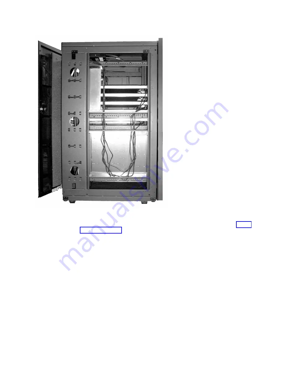
Attention:
To ensure proper air circulation and cooling, filler panels (see “Blank
fillers” on page 228) must be installed in all blank spaces in the rack.
Step 10. Connect switch and device cables
The factory configures the rack and installs all of the director power cables.
The factory does not install switches or routers. These products should be installed
only by qualified personnel.
If you need to install device cables, follow the installation instructions provided
with the component that you are installing.
Step 11. Power on the rack
Perform the following steps to power on the rack:
1.
Plug all power cords into the outlets on the power distribution units (iPDUs).
2.
Plug the power cord of each iPDU into the customer's ac power outlets. Use
only the cords supplied with the rack and iPDUs.
SJ002016
Figure 70. Power cord cabling (rack side view)
Appendix A. SAN rack
221
|
|
|
|
|
|
|
|
|
|
|
|
|
|
|
|
|
Summary of Contents for SAN512B-6
Page 2: ......
Page 8: ...vi SAN512B 6 Installation Service and User Guide...
Page 10: ...viii SAN512B 6 Installation Service and User Guide...
Page 12: ...x SAN512B 6 Installation Service and User Guide...
Page 40: ...16 SAN512B 6 Installation Service and User Guide...
Page 60: ...36 SAN512B 6 Installation Service and User Guide...
Page 128: ...104 SAN512B 6 Installation Service and User Guide...
Page 140: ...116 SAN512B 6 Installation Service and User Guide...
Page 170: ...146 SAN512B 6 Installation Service and User Guide...
Page 184: ...160 SAN512B 6 Installation Service and User Guide...
Page 196: ...172 SAN512B 6 Installation Service and User Guide...
Page 208: ...184 SAN512B 6 Installation Service and User Guide...
Page 258: ...234 SAN512B 6 Installation Service and User Guide...
Page 274: ...250 SAN512B 6 Installation Service and User Guide...
Page 285: ......
Page 286: ...IBM Part Number 01JC152 Printed in USA SC27 8966 02 1P P N 01JC152...


