Procedure
1.
Remove any cables that are inserted into the transceiver.
Note:
If your transceiver has an integrated cable, you cannot remove the cable.
2.
Grasp the transceiver pull tab and gently pull the transceiver straight out from the port.
Note:
Grasp the pull tab near the body of the transceiver to reduce the chances of bending the pull
tab. As the transceiver may be hot, always use the pull tab and avoid touching the transceiver body.
3.
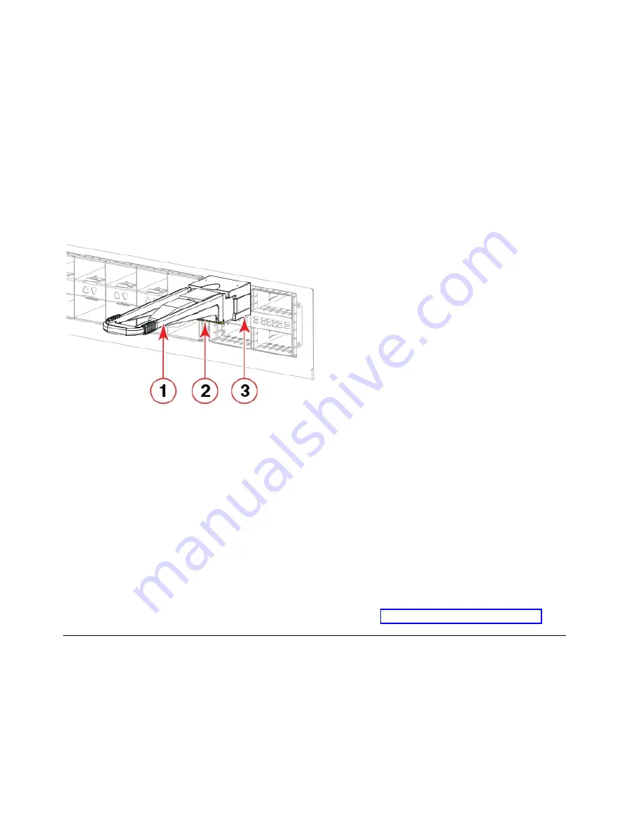
To insert the replacement transceiver, use the pull tab to carefully push the transceiver into the port.
Transceivers are keyed so that they can only be inserted with the correct orientation. If a transceiver
does not slide in easily, ensure that it is correctly oriented. Gently push the correctly oriented QSFP
transceiver until the latching mechanism clicks.
1 - Pull tab
2 - QSFP cable
3 - QSFP transceiver
The port's status LED initially blinks amber after installation, then displays steady amber.
4.
Position a cable so that the key (the ridge on one side of the cable connector) is aligned with the slot
in the transceiver. Insert the cable into the transceiver until the latching mechanism clicks.
Note:
If your transceiver has an integrated cable attached, you will not install a cable.
The port's status LED displays steady amber until both ends of the cable are inserted and the link is
established. When the link is fully established, the LED displays steady green.
Note:
Cables are keyed so that they can be inserted in only one way. If a cable does not slide in
easily, ensure that it is correctly oriented.
5.
Organize cables to avoid covering LEDs and air vents. Refer to “Cable management” on page 73.
Verifying the operation of new transceivers
About this task
You can use the following commands to verify if the transceivers are working correctly:
v
sfpShow
v
switchShow
v
switchshow-slot
slot, where slot is slot number
v
switchshow -qsfp
Figure 43. Installing a QSFP optical transceiver into blade port
78
SAN256B-6 Installation, Service, and User Guide
Summary of Contents for SAN256B-6
Page 6: ...vi SAN256B 6 Installation Service and User Guide...
Page 10: ...x SAN256B 6 Installation Service and User Guide...
Page 22: ...xxii SAN256B 6 Installation Service and User Guide...
Page 24: ...xxiv SAN256B 6 Installation Service and User Guide...
Page 34: ...6 SAN256B 6 Installation Service and User Guide...
Page 72: ...44 SAN256B 6 Installation Service and User Guide...
Page 92: ...64 SAN256B 6 Installation Service and User Guide...
Page 108: ...80 SAN256B 6 Installation Service and User Guide...
Page 152: ...124 SAN256B 6 Installation Service and User Guide...
Page 162: ...134 SAN256B 6 Installation Service and User Guide...
Page 198: ...170 SAN256B 6 Installation Service and User Guide...
Page 206: ...178 SAN256B 6 Installation Service and User Guide...
Page 210: ...182 SAN256B 6 Installation Service and User Guide...
Page 214: ...186 SAN256B 6 Installation Service and User Guide...
Page 218: ...190 SAN256B 6 Installation Service and User Guide...
Page 258: ...230 SAN256B 6 Installation Service and User Guide...
Page 278: ...250 SAN256B 6 Installation Service and User Guide...
Page 286: ...258 SAN256B 6 Installation Service and User Guide...
Page 289: ...WWN card power down replacement 156 Index 261...
Page 290: ...262 SAN256B 6 Installation Service and User Guide...
Page 291: ......
Page 292: ...IBM Part Number 01JC333 Printed in USA SC27 8967 03 1P P N 01JC333...


