


b.
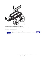
Pull out the memory riser from the slot by holding onto the latches.
c.
Place the memory riser on an ESD mat.
4.
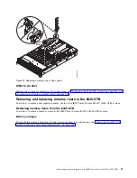
If applicable, move the memory DIMM from the removed riser onto the replacement memory riser.
For instructions, see “Removing and replacing memory DIMM in the 8335-GTB” on page 70.
Replacing memory risers in the 8335-GTB
Learn how to replace memory risers in the IBM Power System S822LC (8335-GTB) system.
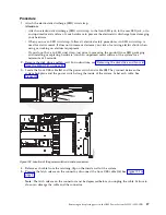
Procedure
1.
Ensure that you have the electrostatic discharge (ESD) wrist strap attached. If not, attach it now.
2.
To replace the memory riser, complete the following steps:
a.
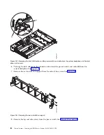
Ensure that the release latches are open to about a 60-degree angle as shown in Figure 94 on page
78.
b.
Align the memory riser with the connector.
c.
Press the memory riser firmly into the connector.
d.
Press the release latches into the closed position. See (A) in Figure 94 on page 78.
Figure 93. Removing a memory riser from the system
Removing and replacing parts in the IBM Power System S822LC (8335-GTB)
77
Summary of Contents for S822LC
Page 1: ...Power Systems Servicing the IBM Power System S822LC 8335 GTB IBM ...
Page 2: ......
Page 3: ...Power Systems Servicing the IBM Power System S822LC 8335 GTB IBM ...
Page 16: ...xiv Power Systems Servicing the IBM Power System S822LC 8335 GTB ...
Page 204: ...188 Power Systems Servicing the IBM Power System S822LC 8335 GTB ...
Page 242: ...226 Power Systems Servicing the IBM Power System S822LC 8335 GTB ...
Page 243: ......
Page 244: ...IBM ...


