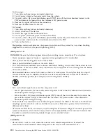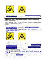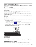
CAUTION:
Hazardous energy present. Voltages with hazardous energy might cause heating when
shorted with metal, which might result in splattered metal, burns, or both. (L005)
2.
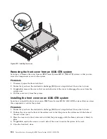
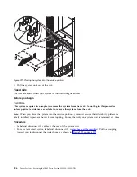
At the rear of the system, loosen the cover screw (A) that fastens the cover to the chassis.
3.
While pressing down on latch (B) and touch point (C), slide the cover (D) towards the rear of the
system unit. When the front of the service access cover clears the upper frame ledge, lift the cover up
and off the system unit.
Attention:
For proper cooling and airflow, replace the cover before you power on the system.
Installing the service access cover on an 8335-GTB system
Learn how to install the service access cover on a rack-mounted IBM Power System S822LC (8335-GTB)
system.
About this task
Attention:
For safety, airflow purposes and thermal performance, the service access cover must be
installed and fully seated prior to powering the system on.
Procedure
1.
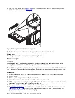
Place the cover (A) on the system unit such that the alignment pins on the cover are aligned to the
slots on the chassis. Slide the cover to the front of the system until the blue release latch (B) locks in
to place as shown in Figure 220 on page 204.
2.
Fasten the cover screw (C) at the rear of the cover.
Figure 219. Removing the cover
Common procedures for servicing or installing features
203
Summary of Contents for S822LC
Page 1: ...Power Systems Servicing the IBM Power System S822LC 8335 GTB IBM ...
Page 2: ......
Page 3: ...Power Systems Servicing the IBM Power System S822LC 8335 GTB IBM ...
Page 16: ...xiv Power Systems Servicing the IBM Power System S822LC 8335 GTB ...
Page 204: ...188 Power Systems Servicing the IBM Power System S822LC 8335 GTB ...
Page 242: ...226 Power Systems Servicing the IBM Power System S822LC 8335 GTB ...
Page 243: ......
Page 244: ...IBM ...


