


2. Copy the
/usr/share/modems/modem_f.cfg
file to a new file with a different name
(for example
modem_fx.cfg
).
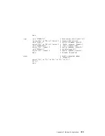
3. In the new file (
modem_fx.cfg
), change the line
Send "ATE0T\r"
to
Send
"ATcccE0T\r"
where ccc is the added command as specified your modem manual,
as follows:
Change the third line of each of the following stanzas:
v
condout
v
condin
v
ripo
4. Save the changes.
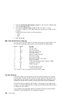
IBM 7852-400 DIP Switch Settings
If you are using a 7852-400 modem to enable service processor communications, the
DIP (dual inline package) switches must be set according to the following table.
Switch
Position
Function
1
Up
Force DTR
2
Up
Flow Control &E4
3
Down
Result Codes Enabled
4
Down
Modem Emulation Disabled
5
Up
Auto Answer Enabled
6
Up
Maximum Throughput Enabled
7
Up
RTS Normal Functions
8
Down
Enable Command Mode
9
Down
Remote Digital Loopback Test Enabled
10
Up
Dial-Up Line Enabled
11
*Up
AT Responses Enabled (Extended Responses Disabled)
12
*Down
Asynchronous Operation
13
Up
28.8KB Line Speed
14
Up
15
Up
CD and DSR Normal Functions
16
Up
2-Wire Leased Line Enabled
* Only switches 11 and 12 are changed from the factory default settings.
Xon/Xoff Modems
Some early modems assume software flow control (Xon/Xoff) between the computer
and the modem. Modems with this design send extra characters during and after the
transmitted data. The service processor cannot accept these extra characters. If your
configuration includes such a modem, your functional results may be unpredictable.
The sample modem configuration files included in this package do not support these
modems, so custom configuration files are necessary. The Anchor Automation 2400E is
an example of such a modem.
Iif you experience unexplainable performance problems that may be due to Xon/Xoff
characters, it is recommended that you upgrade your modem.
296
Service Guide
Summary of Contents for RS/6000 44P Series 270
Page 1: ...RS 6000 44P Series Model 270 Service Guide SA38 0572 02 ...
Page 10: ...x Service Guide ...
Page 14: ...xiv Service Guide ...
Page 16: ...xvi Service Guide ...
Page 20: ...Rear View 1 2 3 4 5 6 7 8 9 11 12 13 14 15 16 10 17 18 19 2 Service Guide ...
Page 44: ...26 Service Guide ...
Page 164: ...146 Service Guide ...
Page 204: ...186 Service Guide ...
Page 247: ...b Slide the covers to the rear and remove Chapter 9 Removal and Replacement Procedures 229 ...
Page 288: ...270 Service Guide ...
Page 290: ...1 2 3 4 5 6 7 8 9 10 11 12 13 14 15 16 17 18 19 21 20 22 23 24 25 272 Service Guide ...
Page 294: ...Keyboards and Mouse 276 Service Guide ...
Page 296: ...Keyboards and Mouse Black 278 Service Guide ...
Page 298: ...Power Cables 1 2 3 4 5 6 7 8 9 10 11 280 Service Guide ...
Page 300: ...282 Service Guide ...
Page 302: ...284 Service Guide ...
Page 304: ...286 Service Guide ...
Page 310: ...292 Service Guide ...
Page 338: ...320 Service Guide ...
Page 345: ......
Page 346: ... Printed in U S A September 2001 SA38 0572 02 ...