


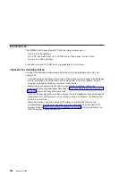


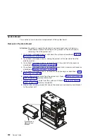


Replacement of Memory Modules
1. With one hand, touch any metal surface of the chassis to minimize static electrical
charges, and then pick up the memory module.
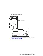
2. Locate the memory module connector on the memory card.
Note:
Memory modules must be installed in pairs and in the correct slot
configuration. (Slots J1 and J2, J3 and J4, J5 and J6, and so on.)
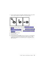
3. Insert the memory module firmly into the connector.
4. Secure the memory module with the locking tabs located at each end of the
connector.
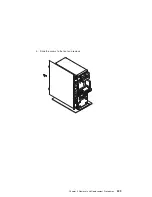
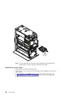
5. Replace the memory card into the system unit. See “Replacement of Memory
Cards” on page 233 for more information.
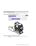
6. Replace the processor and memory card cover as described in “Replacement of
Processor and Memory Card Cover” on page 231.
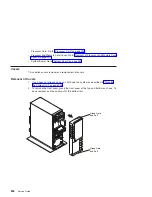
7. Replace the system unit covers as described in “Replacement of Covers” on
Locking Tabs
238
Service Guide
Summary of Contents for RS/6000 44P Series 270
Page 1: ...RS 6000 44P Series Model 270 Service Guide SA38 0572 02 ...
Page 10: ...x Service Guide ...
Page 14: ...xiv Service Guide ...
Page 16: ...xvi Service Guide ...
Page 20: ...Rear View 1 2 3 4 5 6 7 8 9 11 12 13 14 15 16 10 17 18 19 2 Service Guide ...
Page 44: ...26 Service Guide ...
Page 164: ...146 Service Guide ...
Page 204: ...186 Service Guide ...
Page 247: ...b Slide the covers to the rear and remove Chapter 9 Removal and Replacement Procedures 229 ...
Page 288: ...270 Service Guide ...
Page 290: ...1 2 3 4 5 6 7 8 9 10 11 12 13 14 15 16 17 18 19 21 20 22 23 24 25 272 Service Guide ...
Page 294: ...Keyboards and Mouse 276 Service Guide ...
Page 296: ...Keyboards and Mouse Black 278 Service Guide ...
Page 298: ...Power Cables 1 2 3 4 5 6 7 8 9 10 11 280 Service Guide ...
Page 300: ...282 Service Guide ...
Page 302: ...284 Service Guide ...
Page 304: ...286 Service Guide ...
Page 310: ...292 Service Guide ...
Page 338: ...320 Service Guide ...
Page 345: ......
Page 346: ... Printed in U S A September 2001 SA38 0572 02 ...