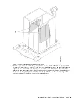

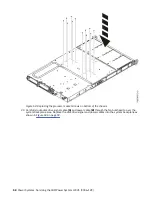

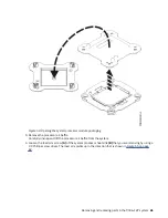


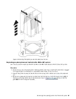

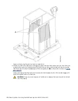
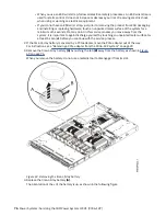


Figure 58. Locking the system processor module into the tool
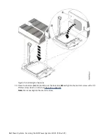
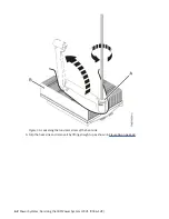
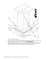
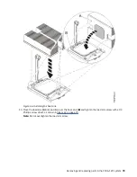
10. Hold the outside of the tool and lift the tool and system processor module from the socket. Place
them at an angle on the top cover of the system processor module packaging as shown in Figure 59
on page 66.
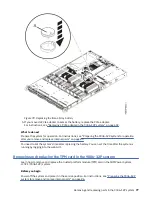
Setting the system processor module at an angle on the top cover of the system processor module
packaging will make it easier to pick up and place in the packaging after you replace the system
processor module.
Removing and replacing parts in the 9006-12P system 65
Summary of Contents for Power System LC921 9006-12P
Page 1: ...Power Systems Servicing the IBM Power System LC921 9006 12P IBM...
Page 14: ...xiv Power Systems Servicing the IBM Power System LC921 9006 12P...
Page 118: ...104 Power Systems Servicing the IBM Power System LC921 9006 12P...
Page 120: ...106 Power Systems Servicing the IBM Power System LC921 9006 12P...
Page 131: ......
Page 132: ...IBM...


