

IBM Ethernet Switch J48E Quick Start
Rev 03
To install the switch in a four-post open rack and configure the switch, you need:
Phillips (+) screwdriver, number 2
6 flat-head 4-40 mounting screws (provided)
12 flat-head 4x6-mm Phillips mounting screws (provided)
One pair of front brackets (either flush brackets or 2-inch-recess brackets), one pair of
side-rail brackets, and one pair of rear brackets (provided)
Screws to secure the chassis and the rear brackets to the rack
Power cord with a plug appropriate for your geographical location and a power cord
retainer (provided)
Management host, such as a PC, with an Ethernet port
Ethernet cable (provided)
NOTE:
These instructions apply to four-post open-rack installation only. For cabinet, wall,
and desk installation instructions and other setup tasks, see the IBM Ethernet Switch J48E
documentation at
http://www.ibm.com/systems/support/networking
.
Part 1: Install a Power Supply in the Switch (If It Is Not Installed)
To install each power supply in the switch chassis:
1.
Remove the power supply from the bag. Take care not to touch power supply
components, pins, leads, or solder connections.
2.
Push down on the locking lever on the left front of the power supply until it is in its
lowest position (see the figure in Part 3 for the location of the locking lever). You
might need to loosen the locking lever screw to move the lever.
3.
Using both hands, place the power supply in the power supply slot on the rear panel
of the switch and slide it in until it is fully seated.
4.
Push the locking lever up to its highest position (this action might pull the power
supply in). Tighten the locking lever screw using the Phillips screwdriver, number 2.
Part 2: Install the Switch
See the IBM Ethernet Switch J48E documentation for details about these tasks.
1.
Attach either the flush brackets or 2-inch-recess brackets to the side-rail brackets with
the 4-40 mounting screws.
2.
Place the switch on a flat, stable surface, align the side-rail brackets along the switch
side panels, and install the brackets on the switch with the 4x6-mm mounting screws.
3.
Make sure the rack is properly secured to the building in its permanent location.
4.
Have one person grasp both sides of the switch, lift it, and position it in the rack so
the side-rail bracket holes align with the threaded holes in the rack front posts. Align
the bottom hole in each bracket with a front post hole until the chassis is level.
5.
Have a second person secure the switch front to the rack.
6.
Slide the rear brackets into the side-rail brackets, and attach each rear bracket to a
rear post.
7.
Ensure that the chassis is level by verifying that all the screws on the rack front are
aligned with the screws on the back of the rack.
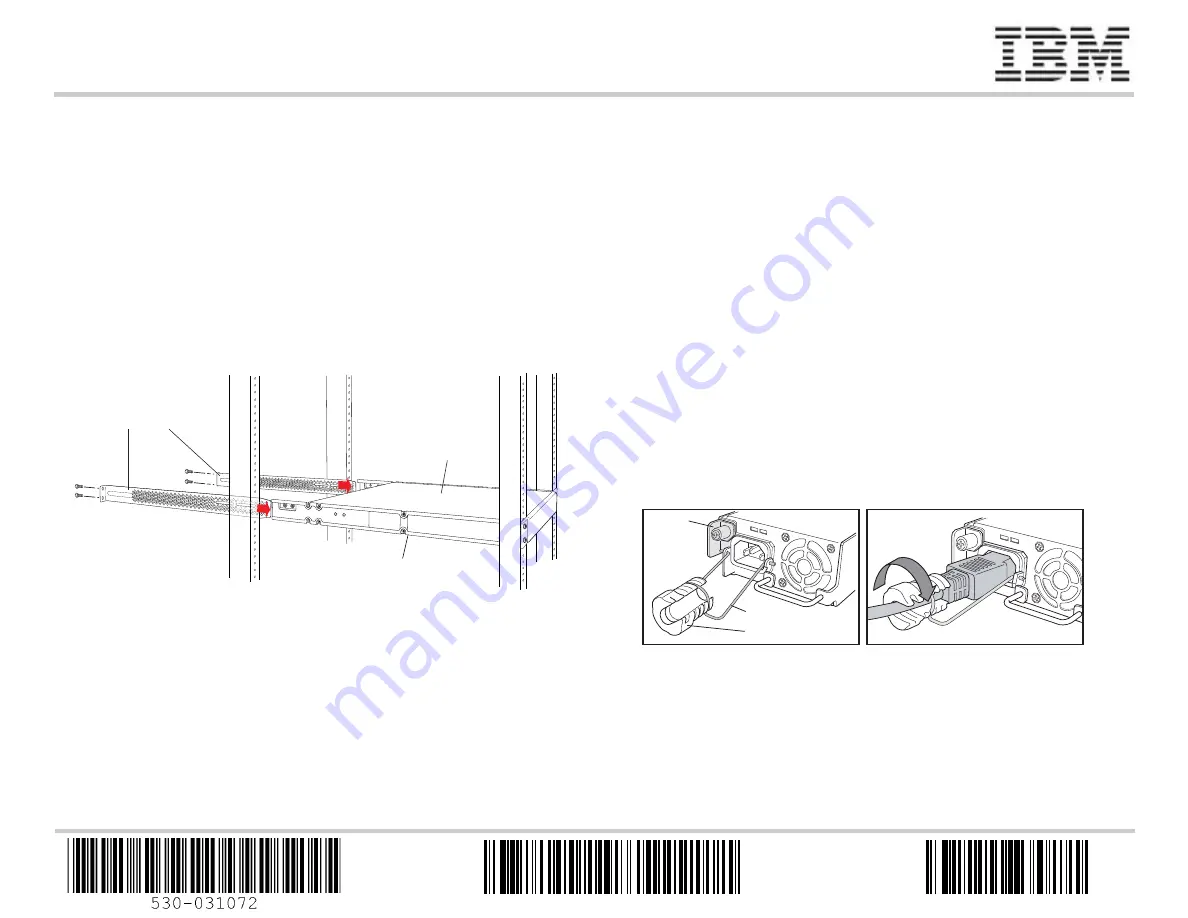
Part 3: Connect Power to the Switch
NOTE:
If you are interconnecting multiple switches as a Virtual Chassis, power on only
one switch—the one you will use as the master.
To connect AC power to the switch:
1.
Squeeze the two sides of the power cord retainer clip, and insert the L-shaped ends of
the wire clip into the holes in the bracket on each side of the AC appliance inlet on the
power supply faceplate.
2.
Insert the coupler end of the power cord into the AC appliance inlet.
3.
Push the cord into the slot in the adjustment nut of the power cord retainer. Turn the
nut until it is tight against the base of the coupler and the slot in the nut is turned 90°
from the top of the switch.
4.
If the AC power source outlet has a power switch, set it to the OFF (0) position.
5.
Insert the power cord plug into the power source outlet.
6.
If the AC power source outlet has a power switch, set it to the ON (|) position.
7.
Repeat these steps for each AC power supply.
g004478
Side-rail
bracket
Switch
Rear brackets
AC
DC
Locking
lever
Tighten
adjustment nut.
Retainer clip
Adjustment nut
AC
DC
g020063
45W7887
GA32-0664-02


