

IBM Ethernet Switch J08E Quick Start
Rev 03
To install and configure an IBM Ethernet Switch J08E you need:
Mechanical lift
Adjustable mounting brackets (4 pieces) with 12 screws total (provided)
40 mounting screws appropriate for your rack—16 screws to attach adjustable
mounting brackets to the rack, 24 screws to attach the preinstalled front-mounting
brackets to the rack, and 4 screws to attach the optional power cord tray to the rack
For each power supply, a power cord with a plug appropriate for your geographical
location and a power cord retainer (provided)
Power cord tray (provided)
Phillips (+) screwdrivers—one appropriate for your rack mounting screw size; a
number 2 for the adjustable bracket mounting screws; a number 1 to remove power
supplies if you will install the switch without using a mechanical lift
Electrostatic discharge (ESD) grounding strap (provided)
Management host, such as a PC, with an Ethernet port
Ethernet cable (provided)
NOTE:
These instructions apply to four-post open-rack installation only. For additional
installation information and other setup tasks, see the IBM Ethernet Switch J08E
documentation at
http://www.ibm.com/systems/support/networking
.
Part 1: Install the Switch
See the IBM Ethernet Switch J08E documentation for details about these tasks.
1.
Attach the grounding strap to your bare wrist and to the ESD point on the chassis.
2.
Make sure the rack is properly secured to the building in its permanent location.
3.
Install the adjustable mounting brackets in the rack in the lowest position that has a
14 U space for the chassis (15 U if you will install the optional power cord tray).
4.
(Optional) Attach the power cord tray to the rack.
5.
Be aware that a base configuration switch as shipped weighs 149 lb (68 kg), a
redundant configuration switch weighs 187 lb (85 kg), and a fully loaded chassis
weighs 284 lb (130 kg). An empty chassis with only the backplane is 89 lb (41 kg).
6.
Using a mechanical lift—or after removing all switch components and having at least
three people available, two for lifting and one for aligning—lift the switch onto the
mounting brackets you installed in the rack.
7.
Position the switch in the rack to align the bracket holes with the threaded rack holes.
8.
Install a mounting screw into each of the front-mounting bracket holes.
9.
If you did not use a mechanical lift, reinstall the switch components.
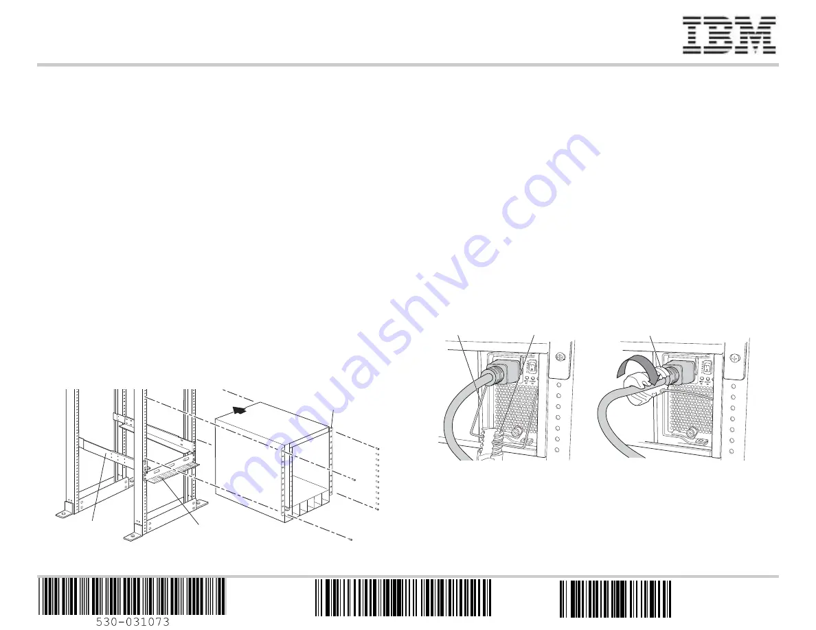
Part 2: Connect Power to the Switch
Power supplies come preinstalled in the chassis. For each power supply:
1.
Ensure that the power supply is fully inserted and latched securely in the chassis.
2.
Flip the
Enable
switch to the Standby position.
3.
Squeeze the sides of the power cord retainer clip. Insert the L-shaped clip ends into
the bracket holes on each side of the AC appliance inlet on the faceplate.
4.
Insert the coupler end of the power cord into the AC appliance inlet.
5.
Push the power cord into the slot in the adjustment nut. Turn the nut until it is against
the base of the coupler and the slot in the nut is turned 90° from the top of the
switch.
6.
If the AC power source outlet has a power switch, set it to the OFF (0) position.
7.
Insert the power cord plug into the power source outlet.
8.
If the AC power source outlet has a power switch, set it to the ON (|) position.
9.
Verify that the
INPUT OK
LED on the power supply faceplate is lit and is on steadily.
10. Flip the power supply
Enable
switch to the “on” position.
11. Repeat Steps 1 through 10 for each installed power supply.
g
020569
Front-mounting
bracket
Power
cord tray
Adjustable
bracket
g020571
Rotate adjustment nut.
Adjustment nut
Retainer clip
GA32-0666-01
45W7368


