background image

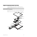
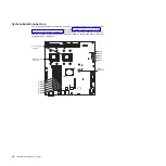
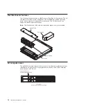
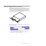
Removing a system-board tray from a 2U chassis

Attention:

When two system-board trays are installed in the chassis, do not

operate the upper system-board tray with the bottom system-board tray removed or
powered off, except for servicing. When the bottom system-board tray is removed
or powered-off, chassis-level system management information is not read correctly.
For example, chassis fan speeds and temperatures might be returned as zero
values. In this situation, the unit will continue to operate normally, since the power
supply and fans are designed to operate independently.

Note:

If two system-board trays are installed in the chassis, they can be removed

independently of each other.

To remove a system-board tray from the chassis, complete the following steps.

1. Read the safety information that begins on page and “Installation guidelines”

on page 17.

2. Turn off the system-board tray and all attached devices (see “Turning off the

system-board tray” on page 15).

3. If external cables are connected to the front of the system-board tray, note

where they are connected; then, remove them.

4. Press in on the two release handles, pull the system-board tray out of the

chassis, and set it on a flat, static-protective surface.

Chapter 3. Installing optional devices

19

Summary of Contents for iDataPlex dx320 6385

Page 1: ...System x iDataPlex dx320 Types 6385 and 6388 User s Guide...

Page 2: ......

Page 3: ...System x iDataPlex dx320 Types 6385 and 6388 User s Guide...

Page 4: ...Safety Information IBM Systems Environmental Notices and User Guide and the IBM Warranty and Support Information documents on the IBM Documentation CD Third Edition June 2011 Copyright IBM Corporatio...

Page 5: ...evices 18 Removing a system board tray from a 2U chassis 19 Removing the system board tray cover 20 Removing a 3 5 inch simple swap hard disk drive 21 Installing a 3 5 inch simple swap hard disk drive...

Page 6: ...ion notices 41 Federal Communications Commission FCC statement 41 Industry Canada Class A emission compliance statement 41 Avis de conformit la r glementation d Industrie Canada 41 Australia and New Z...

Page 7: ...n tuotteen lue turvaohjeet kohdasta Safety Information Avant d installer ce produit lisez les consignes de s curit Vor der Installation dieses Produkts die Sicherheitshinweise lesen Prima di installar...

Page 8: ...there is evidence of fire water or structural damage v Disconnect the attached power cords telecommunications systems networks and modems before you open the device covers unless instructed otherwise...

Page 9: ...es or regulations Statement 3 CAUTION When laser products such as CD ROMs DVD drives fiber optic devices or transmitters are installed note the following v Do not remove the covers Removing the covers...

Page 10: ...button on the device and the power switch on the power supply do not turn off the electrical current supplied to the device The device also might have more than one power cord To remove all electrical...

Page 11: ...us voltage current and energy levels are present inside any component that has this label attached There are no serviceable parts inside these components If you suspect a problem with one of these par...

Page 12: ...x IBM iDataPlex dx320 User s Guide...

Page 13: ...nty For information about the terms of the warranty and getting service and assistance see the Warranty and Support Information document You can obtain up to date information about the server and othe...

Page 14: ...stance v Safety Information This document contains translated caution and danger statements Each caution and danger statement that appears in the documentation has a number that you can use to locate...

Page 15: ...0 MHz microprocessor v 32 MB of RAM v Adobe Acrobat Reader 3 0 or later or xpdf which comes with Linux operating systems Using the Documentation Browser Use the Documentation Browser to browse the con...

Page 16: ...using the Documentation Browser Notices and statements in this document The caution and danger statements in this document are also in the multilingual Safety Information document which is on the IBM...

Page 17: ...rating speed can be adjusted using the BIOS Setup Utility program Integrated functions v Baseboard management controller BMC with Intelligent Platform Management Interface IPMI 2 0 compliant firmware...

Page 18: ...pport Additionally you can view the information locally through a generated text report file You also can copy the log to removable media and view the log from a Web browser v High performance graphic...

Page 19: ...atic restart after a power failure based on the BIOS setting v Boot block recovery v Built in monitoring for fan power temperature and voltage v Customer support center that is available 24 hours a da...

Page 20: ...e the CD go to http www ibm com systems management xpress html Additional information about UpdateXpress is available from the Tools Center at http publib boulder ibm com infocenter toolsctr v1r0 inde...

Page 21: ...ver controls and light emitting diodes LEDs and how to turn the system board tray on and off System board tray components The following illustration shows the major components in the dx320 system boar...

Page 22: ...ols LEDs connectors and power on page 13 for information about the external connectors See the Problem Determination and Service Guide for information about the other system board connectors Microproc...

Page 23: ...itch number Switch button description 1 NMI When this button is pressed it issues a non maskable interrupt NMI to the server This button is functional only when power is connected to the server and th...

Page 24: ...e 2U flex chassis can support two dx320 system board trays Note The illustrations in this document might differ slightly from your hardware Fan assembly cover Fan assembly 2U chassis Power supply 2U c...

Page 25: ...t Ethernet connector When this LED is lit and is amber it indicates that the Ethernet network speed is 100 Mbps When this LED is not lit it indicates that the Ethernet network speed is 10 Mbps Etherne...

Page 26: ...an iDataPlex rack it is connected automatically to power through a power cord that is mounted to the rack rail Turning on the system board tray After you install the system board tray in a chassis the...

Page 27: ...s supported by the operating system v You can turn off the system board tray from the operating system if the operating system supports this feature After an orderly shutdown of the operating system t...

Page 28: ...16 IBM iDataPlex dx320 User s Guide...

Page 29: ...ute the weight of the object equally between your feet Use a slow lifting force Never move suddenly or twist when you lift a heavy object To avoid straining the muscles in your back lift by standing o...

Page 30: ...harge observe the following precautions v Limit your movement Movement can cause static electricity to build up around you v The use of a grounding system is recommended For example wear an electrosta...

Page 31: ...ly and fans are designed to operate independently Note If two system board trays are installed in the chassis they can be removed independently of each other To remove a system board tray from the cha...

Page 32: ...ray on page 15 3 If the system board tray is installed in a chassis remove it see Removing a system board tray from a 2U chassis on page 19 4 Carefully set the system board tray on a flat static prote...

Page 33: ...e system board tray on page 15 3 Remove the filler panel from the simple swap hard disk drive bay 4 Pull the loops of the drive toward each other then pull the drive out of the drive bay Note A hard d...

Page 34: ...e on the outside of the system board tray for at least 2 seconds then remove the hard disk drive from the package Attention Do not press on the top of the drive Pressing the top might damage the drive...

Page 35: ...e with the server Note The default memory operating speed is 533 MHz for Web 2 0 power saving optimization Memory operating speed can be adjusted using the Chipset option in the BIOS Setup Utility pro...

Page 36: ...6 DIMM 5 DIMM 4 DIMM 3 DIMM 2 DIMM 1 SATA 1 SATA 2 SATA 3 SATA 4 To install a DIMM in the system board tray complete the following steps 1 Read the documentation that comes with the DIMM 2 Locate the...

Page 37: ...DIMM so that the DIMM keys align correctly with the connector on the system board 6 Insert the DIMM by applying pressure along the top of the DIMM at both ends simultaneously Make sure that the retain...

Page 38: ...Attention You cannot install the system board tray into the chassis until the cover is installed and closed Do not attempt to override this protection System board tray cover System board tray To rei...

Page 39: ...system board tray see Turning on the system board tray on page 14 4 Make sure that the power on LED on the system board tray operator panel is lit continuously indicating that the system board tray i...

Page 40: ...device you might receive a message that the configuration has changed The BIOS Setup Utility program starts automatically so that you can save the new configuration settings For more information see C...

Page 41: ...rd management controller to update the firmware and sensor data record field replaceable unit SDR FRU data and to remotely manage a network For information about using these programs see Using the bas...

Page 42: ...etup Utility main window taskbar Depending on the version of the BIOS code some taskbar choices might differ slightly from these descriptions v Main Select this choice to view system information such...

Page 43: ...used Memory settings View recognized DIMMs and enable a DIMM after it replaces a failed DIMM NMI auto reboot Configure whether the server automatically restarts when it receives a non maskable interr...

Page 44: ...hority User password If a user password is set when you turn on the server the system startup will not be completed until you type the user password You can use any combination of up to seven characte...

Page 45: ...Note Changes are made periodically to the IBM Web site The actual procedure might vary slightly from what is described in this document 1 Go to http www ibm com systems support 2 Under Product suppor...

Page 46: ...ette drive 4 From a command line type flash and press Enter For the program to interface with the baseboard management controller the parameters in the Intf ini file must be set correctly To modify th...

Page 47: ...uplex of the network and automatically operates at that rate and mode You do not have to set any jumpers or configure the controller However you must install a device driver to enable the operating sy...

Page 48: ...low the instructions on how to apply the updates using documentation that is included in the downloaded files v BIOS code v BMC firmware v FRU SDR data Major components contain VPD code You can select...

Page 49: ...our IBM product The documentation that comes with IBM systems also describes the diagnostic tests that you can perform Most systems operating systems and programs come with documentation that contains...

Page 50: ...M services see http www ibm com services or see http www ibm com planetwide for support telephone numbers In the U S and Canada call 1 800 IBM SERV 1 800 426 7378 Hardware service and support You can...

Page 51: ...s or implied warranties in certain transactions therefore this statement may not apply to you This information could include technical inaccuracies or typographical errors Changes are periodically mad...

Page 52: ...networks nor is it intended to be used in a public services network Processor speed indicates the internal clock speed of the microprocessor other factors also affect application performance CD or DV...

Page 53: ...used in accordance with the instruction manual may cause harmful interference to radio communications Operation of this equipment in a residential area is likely to cause harmful interference in which...

Page 54: ...he product including the fitting of non IBM option cards This product has been tested and found to comply with the limits for Class A Information Technology Equipment according to CISPR 22 European St...

Page 55: ...Chinese Class A warning statement Japanese Voluntary Control Council for Interference VCCI statement Korean Class A warning statement Appendix B Notices 43...

Page 56: ...44 IBM iDataPlex dx320 User s Guide...

Page 57: ...ectronic emission Class A notice 41 environment 5 Ethernet integrated on system board 35 Ethernet connector 13 Ethernet controller configuring 35 Ethernet controller configuration 29 Ethernet transmit...

Page 58: ...upervisor password 32 support web site 37 symmetric multiprocessing 6 system board components 9 connectors 10 jumpers 11 system board tray reinstalling 27 system board tray cover installing 26 removin...

Page 59: ......

Page 60: ...Part Number 90Y5674 Printed in USA 1P P N 90Y5674...

Reviews: