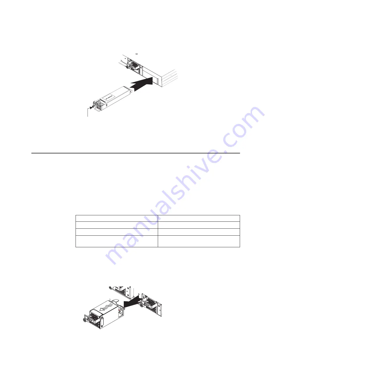
Release latch
2. Connect the power cord to the power supply module and to an AC power
source.
3. Turn on the power at the power source.
4. Make sure that the power supply OK and AC LEDs are green.
Removing and replacing the fan module
The RackSwitch contains up to four hot-swap fan modules.
The switch continues to operate when there is one failed fan module. If one fan
fails, the switch sends an error message. If a second fan fails, the switch sends an
error message, writes a failure log to flash memory, and shuts down.
Each fan module has a green LED that is visible from the rear panel. The LED
shows the status of the fan module, as follows:
Table 15. Fan LED states
LED state
Description
Lit
Fans are operational.
Off
Fan unit has no power.
Flashes
Fan speed has failed. Replace the fan
module.
Removing the fan module
To remove a fan module, complete the following steps:
1. Loosen the retainer screw.
2. Grasp the extractor handle and gently pull the fan module from the slot.
Attention:
Replace the fan module within 5 minutes to avoid overheating the
switch.
Chapter 3. Removing and replacing the RackSwitch and components
41
Summary of Contents for G8052
Page 1: ...IBM System Networking RackSwitch G8052 Installation Guide...
Page 2: ......
Page 3: ...IBM System Networking RackSwitch G8052 Installation Guide...
Page 26: ...12 IBM System Networking RackSwitch G8052 Installation Guide...
Page 48: ...34 IBM System Networking RackSwitch G8052 Installation Guide...
Page 60: ...46 IBM System Networking RackSwitch G8052 Installation Guide...
Page 66: ...52 IBM System Networking RackSwitch G8052 Installation Guide...
Page 74: ...60 IBM System Networking RackSwitch G8052 Installation Guide...
Page 84: ...70 IBM System Networking RackSwitch G8052 Installation Guide...
Page 87: ......
Page 88: ...Part Number 00AY392 Printed in USA 1P P N 00AY392...


