Chapter 5. Installing options
53
Using the LVD SCSI backplane
Your server contains hardware that enables you to replace a failed hard disk drive
without turning off the server. Therefore, you have the advantage of continuing to
operate your system while a hard disk drive is removed or installed. These drives are
known as hot-swap drives. The hot-swap drives are attached to a hot-swap hard disk
drive backplane. The backplane is a printed circuit board behind the drive bays. For
more information on drive bays and drive installation, see “Installing internal drives”
on page 60.
As shipped, the LVD SCSI hot-swap hard disk drive backplane supports a split, dual-
channel configuration. You can install a maximum of 10 slim-high, hot-swap hard
disk drives. You can attach five drives to each half of the backplane. These drives must
be low voltage differential (LVD) hard disk drives that operate at 160 MB per second
or lower.
You can configure the channels on the SCSI backplane in one of two ways:
•
You can configure each SCSI channel (bus) independently. This is the standard
backplane configuration. In this configuration:
— The hard disk drives in the upper half of the backplane are attached to
channel A through a SCSI cable that comes attached to the SCSI backplane.
— The hard disk drives in the lower half of the backplane are attached to
channel B through a second optional SCSI cable. One end of this second SCSI
cable comes attached to the SCSI channel B connector on the backplane. The
other end of this cable is folded and restrained with a clamp.
When you are installing hot-swap hard disk drives in the standard backplane
configuration, attach the first five to channel A; then, attach the remainder to
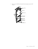
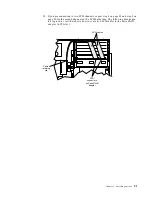
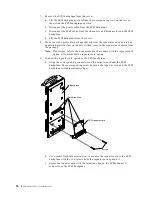
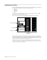
channel B. Refer to the illustration in this section for the SCSI channel connector
locations.
•
You can choose to configure the SCSI backplane as a single 10-drive SCSI channel.
To do this, you must install an optional SCSI repeater card as described in
“Installing a SCSI repeater card” on page 54.
Notes:
1.
The LVD SCSI backplane is also known as the SCSI backplane or the hot-swap
hard disk drive backplane.
2.
Table 10 on page 85 lists the SCSI identifiers (IDs) for the LVD SCSI backplane and
the hot-swap hard disk drives that are attached to SCSI channels A and B.
3.
Carefully route all cables so that they do not become damaged.
4.
Cable identifiers are printed on the cables that come with your server and
options. Use these identifiers to attach the cables to the correct connectors. For
example, the hard disk drive cables are labeled "HDD".
5.
For information on cabling options and using the LVD SCSI backplane, refer to
the documentation that comes with the option kit.
6.
For additional information on cabling the ServeRAID adapter, see “Cabling
example for the ServeRAID adapter” on page 47.
7.
The illustrations in this document might differ slightly from your hardware.
Summary of Contents for eServer 250 xSeries
Page 1: ...User s Reference xSeries 250...
Page 2: ......
Page 3: ...IBM IBM xSeries 250 User s Reference SC21 P902 00...
Page 8: ...vi IBM xSeries 250 User s Reference...
Page 14: ...xii IBM xSeries 250 User s Reference...
Page 24: ...10 IBM xSeries 250 User s Reference...
Page 36: ...22 IBM xSeries 250 User s Reference...
Page 108: ...94 IBM xSeries 250 User s Reference...
Page 185: ......
Page 186: ...IBM Part Number 21P9020 Printed in the United States of America 21P9 2...


