Service Access Cover Removal (Model 6E4)
To remove the service access cover, do the following:
1. Remove the Model 6E4’s outer side cover as described in “Outer Side Cover
Removal (Model 6E4)” on page 56.
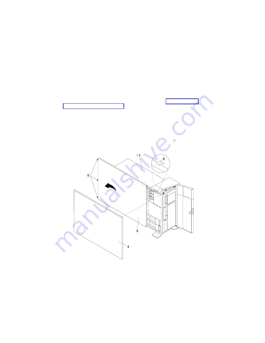
2. Loosen the three captive thumbscrews located on the rear of the cover. See the
following illustration for thumbscrew locations.
3. Slide the cover toward the rear of the system drawer. After the front of the service
access cover has cleared the front chassis ledge, lift the cover out of the system.
Attention:
For proper cooling and airflow, replace the cover before turning on the
system. Operating the system for extended periods of time (over 30 minutes) with the
cover removed might damage the system components.
1 Model 6E4
4 Outer Side Cover
2 Service Access Cover Locking Tab
5 Thumbscrews
3 Service Access Cover
Chapter 4. Installing Options
57
Summary of Contents for @Server pSeries 630 6C4
Page 1: ...pSeries 630 Model 6C4 and Model 6E4 Installation Guide SA38 0605 01 ERserver IBM...
Page 2: ......
Page 3: ...pSeries 630 Model 6C4 and Model 6E4 Installation Guide SA38 0605 01 ERserver IBM...
Page 12: ...x Eserver pSeries 630 Model 6C4 and Model 6E4 Installation Guide...
Page 14: ...xii Eserver pSeries 630 Model 6C4 and Model 6E4 Installation Guide...
Page 22: ...6 Eserver pSeries 630 Model 6C4 and Model 6E4 Installation Guide...
Page 64: ...48 Eserver pSeries 630 Model 6C4 and Model 6E4 Installation Guide...
Page 148: ...132 Eserver pSeries 630 Model 6C4 and Model 6E4 Installation Guide...
Page 152: ...136 Eserver pSeries 630 Model 6C4 and Model 6E4 Installation Guide...
Page 156: ...140 Eserver pSeries 630 Model 6C4 and Model 6E4 Installation Guide...
Page 166: ...150 Eserver pSeries 630 Model 6C4 and Model 6E4 Installation Guide...
Page 179: ......
Page 180: ...IBMR Part Number 00P3937 Printed in U S A August 2002 SA38 0605 01 1P P N 00P3937...


