background image

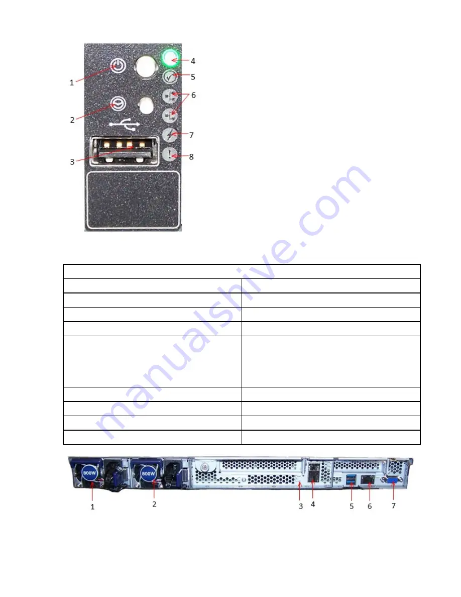
Figure 2. Right Front Panel Detail – SFF ODP

Table 7. Front Panel Features for 2.5” SFF Drives
Item

Description

1

Power On/Off

2

UID

3

USB 2.0 (1x) port

4

System Power LED
• Off: There is no AC power to the appliance
• Green: AC power is on and power is supplied to

all components.

5

UID

6

Network Activity

7

Power Fault

8

System Health

Figure 3. Rear Panel Features

6  IBM Cloud Object Storage System: A10/C10/M10 Appliance Manual

Summary of Contents for A10

Page 1: ...IBM Cloud Object Storage System Version 3 14 12 A10 C10 M10 Appliance Manual 4957 A10 4958 A10 4957 C10 4958 C10 4957 M10 4958 M10 IBM...

Page 2: ...he information in the IBM Environmental Notices and User Guide provided on a DVD This edition applies to IBM Cloud Object Storage System Accesser A10 C10 M10 and is valid until replaced by new edition...

Page 3: ...ents 1 Chapter 2 Specifications and requirements 3 Appliance specifications 3 Requirements 4 Chapter 3 Appliance physical interface 5 Chapter 4 Install the appliance into a rack 9 Prepare for installa...

Page 4: ...iv...

Page 5: ...ail from front of rack 15 11 Unmount rear of rack 15 12 Detaching rail from rear of rack 16 13 Pulling out slide rails 17 14 Inserting appliance into slide rails 17 15 Securing appliance in slide rail...

Page 6: ...SU 29 32 Replacing a drive 30 33 Installing a drive in the front panel 30 34 Removing a fan 31 35 1U fan enumeration 31 36 Install a fan 31 37 Removing a riser card 32 38 Replacing a riser card 32 39...

Page 7: ...fications 3 4 Cabling requirements for the appliance 4 5 Disk drive LED status 5 6 Front Panel Features for 2 5 SFF Drives 5 7 Front Panel Features for 2 5 SFF Drives 6 8 Front Panel Features for 2 5...

Page 8: ...viii...

Page 9: ...disk drives prior to attempting this installation Only personnel proficient in working with computer hardware and disk drives should attempt to install this appliance After all appliances have been in...

Page 10: ...x IBM Cloud Object Storage System A10 C10 M10 Appliance Manual...

Page 11: ...ollowing precautions Electrical voltage and current from power telephone and communication cables are hazardous To avoid a shock hazard If IBM supplied the power cord s connect power to this unit only...

Page 12: ...es To connect 1 Turn off everything unless instructed otherwise 2 Attach all cables to the devices 3 Attach the signal cables to the connectors 4 For AC power attach the power cords to the outlets 5 F...

Page 13: ...nded to prevent an electrical shock R00l part 1 of 2 CAUTION Do not install a unit in a rack where the internal rack ambient temperatures will exceed the manufacturer s recommended ambient temperature...

Page 14: ...xternal power supplies and safety data sheets Electromagnetic Compatibility Notices Class A Notices The following Class A statements apply to IBM products and their features unless designated as elect...

Page 15: ...Germany Notice Safety and environmental notices xv...

Page 16: ...Technology Industries Association JEITA Notice Japan Voluntary Control Council for Interference VCCI Notice Korea Notice People s Republic of China Notice Russia Notice xvi IBM Cloud Object Storage Sy...

Page 17: ...1 5 Product description Models A10 C10 M10 J10 J11 J12 Declared A weighted sound power level LWA m B Declared A Weighted Sound Pressure Level LpA m dB Statistical adder for verification Kv B Operatin...

Page 18: ...can be computed from the sum of LWA m and Kv 4 All measurements made in conformance with ISO 7779 and declared in conformance with ISO 9296 5 B dB abbreviations for bels and decibels respectively 1 B...

Page 19: ...mation Technical support contacts For more information on the product or help with troubleshooting contact IBM Support at ibm com mysupport or visit the Directory of worldwide contacts Copyright IBM C...

Page 20: ...xx IBM Cloud Object Storage System A10 C10 M10 Appliance Manual...

Page 21: ...cautions must be followed to protect yourself and the appliance Do not work alone with high voltage components Be aware of the locations of the power switch on the appliance and the room s emergency p...

Page 22: ...m your body They are excellent metal conductors that can create short circuits and harm you if they come into contact with printed circuit boards or areas where power is present 2 IBM Cloud Object Sto...

Page 23: ...rd dual port 10GbE SFP BMC IPMI 2 0 with virtual media over LAN and KVM over LAN support Front I O USB 2 0 1x Rear I O USB 3 0 2x VGA 1x 10GbE 2x IPMI 1x Cooling 6 1 redundant hot swappable fans Power...

Page 24: ...D M10 AJ5S 2 Required 960GB SATA SSD RAID Controller M10 AJ5U 1 Required Internal RAID card Data Disk Controller C10 AJ5V 1 Required External SAS HBA card 1 All A10 Accessers are configured with 192GB...

Page 25: ...LED status Status Color No drive present Off Activity Flashing Green Idle no activity Off Fault Amber CAUTION To maintain proper airflow and cooling inside the chassis all drive slots must have a disk...

Page 26: ...1 Power On Off 2 UID 3 USB 2 0 1x port 4 System Power LED Off There is no AC power to the appliance Green AC power is on and power is supplied to all components 5 UID 6 Network Activity 7 Power Fault...

Page 27: ...anagement Ethernet IPMI port 7 VGA port System Components The following figure identifies the components of the system and displays the locations of the components which you can replace CRU Figure 4 S...

Page 28: ...IMM Slots1 4 CMOS battery 5 PCIe Slot for C10 External Disk Controller M10 Raid Card 6 Not used 7 PSU 2x 8 CPU Heat Sink and CPU1 9 Asset Tag 1 Field Replaceable Unit FRU only 8 IBM Cloud Object Stora...

Page 29: ...the rack for sufficient airflow and ease in servicing Mechanical loading Mount the equipment into a rack so that a hazardous condition does not arise due to uneven mechanical loading Install heavier...

Page 30: ...the equipment installation If necessary reduce the weight of the enclosure by removing the hard disk drives and power supply units during installation When using the lifting straps keep them even and...

Page 31: ...ly 1 Select where you want to place the appliance into the rack 2 Each slide rail is marked with FRONT to indicate the front of the rail and either a R front right or a L front left to indicate the wh...

Page 32: ...the Front locking bracket and align the slide rail pins with the holes in the selected U on the front of the rack and insert into the front of the rack as shown in the following figure 12 IBM Cloud O...

Page 33: ...e rail into front of rack 6 Push the Front locking bracket over the rail until it latches into place as shown in the following figure Figure 8 Attaching rail to front of rack Chapter 4 Install the app...

Page 34: ...me height Unmount the slide rail rack Assembly 1 Release the front of the slide rail from the rack first by pushing out the Front locking bracket as shown in the following figure Figure 9 Unmount fron...

Page 35: ...ar of the slide rail next by pushing out the slide rail from the rack as shown in the following figure Figure 11 Unmount rear of rack 4 Pull slide rail away from the rack to detach as shown in the fol...

Page 36: ...rail from rear of rack Installing the appliance into the rack 1 Pull the slide rails forward until they click into place as shown in the following figure 16 IBM Cloud Object Storage System A10 C10 M1...

Page 37: ...s on the slide rails as shown in the following figure Figure 14 Inserting appliance into slide rails 3 Slide the appliance down until the rear nail heads slip into the two rear slots and then slowly l...

Page 38: ...ils 4 Push up the side lock to push the appliance all the way into the rack until it clicks into place as shown in the following figure Figure 16 Unlock Inner membrane of Rail 18 IBM Cloud Object Stor...

Page 39: ...he appliance Removing the appliance from the rack 1 Unscrew the thumbscrews on each side of the rack to unsecure the appliance as shown in the following figure Figure 18 Detaching thumbscrews from fro...

Page 40: ...ock the rail as shown in the following figure Figure 20 Releasing appliance from rail 4 Place your hands underneath the appliance and carefully push it up and lift it off the rails as shown in the fol...

Page 41: ...emove the appliance release the side lock and push the inner member into the rail and the rail back into the rack until it clicks into place as shown in the following figure Figure 22 Sliding rail bac...

Page 42: ...22 IBM Cloud Object Storage System A10 C10 M10 Appliance Manual...

Page 43: ...tempt to modify or use the AC power cord if it is not the exact type required to fit into the grounded power outlet Power down the appliance 1 Check the color of the Power Status LED a Green means tha...

Page 44: ...CAUTION To avoid data loss or damage to your operating system you should always invoke a graceful shutdown of the operating system 24 IBM Cloud Object Storage System A10 C10 M10 Appliance Manual...

Page 45: ...on the appliance and avoid injury from any metal edges Electrostatic discharge ESD strap or other grounding equipment such as a grounded mat CAUTION Do not use of any sort of hammer to secure the rai...

Page 46: ...cover with the chassis then slide the cover toward the front of the chassis until it is secured 2 Tighten the thumbscrew at the rear of the chassis to lock the appliance cover in place 3 To replace t...

Page 47: ...ht damage them Remove or Replace the Fan Cover This section covers how to access the fans and remove the fan cover Note Because the fans are hot swappable you do not have to power off the appliance be...

Page 48: ...g figure Figure 30 Secure fan cover Replace appliance components This section describes the procedures for replacing appliance components Replacing the power supply unit PSU This appliance has two mai...

Page 49: ...lever for quick installation and removal Note Because your drives are hot pluggable it is unnecessary to power off your system in order to replace them Note Note Make sure you take note of the orient...

Page 50: ...c Repeat the previous steps to assemble and install all other drives into the empty front drive slots Remove and install a fan This section describes the process for removing and installing fans Note...

Page 51: ...sure the fan connector is seated properly in the connection socket on the slot to secure it c Replace the fan cover see the section on Removing or Replacing the Fan Cover Figure 36 Install a fan Remov...

Page 52: ...tor ports from the riser assembly as shown in the following figure Figure 38 Replacing a riser card 5 To install PCIe riser cards follow these steps as shown in the following figure a Power off the sy...

Page 53: ...e CMOS Battery If the server no longer automatically displays the correct date and time you many need to replace the battery that provides power to the real time clock CAUTION The battery contains lit...

Page 54: ...pop out slightly from the socket as shown in the following figure Figure 41 Releasing CMOS battery from motherboard 3 Grasp the battery and remove it from the socket as shown in the following figure F...

Page 55: ...les then power on the system Note Make sure you note the orientation of the polarity of the battery before you remove it so that you can insert it with the same orientation as shown in the following f...

Page 56: ...36 IBM Cloud Object Storage System A10 C10 M10 Appliance Manual...

Page 57: ...Japan Ltd 19 21 Nihonbashi Hakozakicho Chuo ku Tokyo 103 8510 Japan INTERNATIONAL BUSINESS MACHINES CORPORATION PROVIDES THIS PUBLICATION AS IS WITHOUT WARRANTY OF ANY KIND EITHER EXPRESS OR IMPLIED...

Page 58: ...is entirely coincidental COPYRIGHT LICENSE This information contains sample application programs in source language which illustrate programming techniques on various operating platforms You may copy...

Page 59: ...n your country for connection by any means whatsoever to interfaces of public telecommunications networks Further certification may be required by law prior to making any such connection Contact an IB...

Page 60: ...40 IBM Cloud Object Storage System A10 C10 M10 Appliance Manual...

Page 61: ......

Page 62: ...IBM...

Reviews: