background image

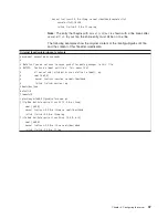
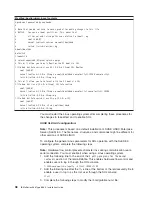
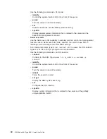
kernel


/vmlinuz-2.4.9-e.12smp


ro


root=/dev/hda6


console=tty1


console=ttyS1,19200


initrd


/initrd-2.4.9-e.12smp.img


Note:


The


entry


that


begins


with


kernel


/vmlinuz


is


shown


with


a


line


break


after


console=tty1

.


In


your


file,


the


entire


entry


must


all


be


on


one


line.


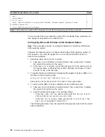
The


following


examples


show


the


original


content


of


the


/boot/grub/grub.conf


file


and


the


content


of


this


file


after


modification.


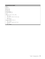
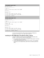
Original


/boot/grub/grub.conf


contents


#grub.conf


generated


by


anaconda


#


#


Note


that


you


do


not


have


to


rerun


grub


after


making


changes


to


this


file


#


NOTICE:


You


have


a


/boot


partition.


This


means


that


#


all


kernel


and


initrd


paths


are


relative


to


/boot/,


eg.


#


root


(hd0,0)


#


kernel


/vmlinuz-version


ro


root=/dev/hda6


#


initrd


/initrd-version.img


#boot=/dev/hda


default=0


timeout=10


splashimage=(hd0,0)/grub/splash.xpm.gz


title


Red


Hat


Enterprise


Linux


ES


(2.4.9-e.12smp)


root


(hd0,0)


kernel


/vmlinuz-2.4.9-e.12smp


ro


root=/dev/hda6


initrd


/initrd-2.4.9-e.12smp.img


title


Red


Hat


Enterprise


Linux


ES-up


(2.4.9-e.12)


root


(hd0,0)


kernel


/vmlinuz-2.4.9-e.12


ro


root=/dev/hda6


initrd


/initrd-2.4.9-e.12.img


Chapter


4.


Configuring


the


server


37

Summary of Contents for 8863 - eServer xSeries 366

Page 1: ...lity Documentation CD Installation Guide Go to the Server Support flowchart Cable the server and options Start the server Install options Drives Microprocessors Adapters Memory Did the server start co...

Page 2: ...connections and verify that all optional devices you installed are on the ServerProven list You can view the ServerProven list at http www ibm com pc compat Server working properly Problem solved Prob...

Page 3: ...IBM xSeries 366 Type 8863 Installation Guide...

Page 4: ...and the Warranty and Support Information document on the IBM xSeries Documentation CD Second Edition August 2005 Copyright International Business Machines Corporation 2005 All rights reserved US Gover...

Page 5: ...1 Completing the installation 23 Connecting the cables 23 Updating the server configuration 24 Chapter 3 Server controls connectors LEDs and power 25 Front view 25 Rear view 27 Server power features 2...

Page 6: ...ing the documentation 67 Getting help and information from the World Wide Web 68 Software service and support 68 Hardware service and support 68 Notices 69 Edition notice 69 Trademarks 70 Important no...

Page 7: ...alleert eerst de veiligheidsvoorschriften Ennen kuin asennat t m n tuotteen lue turvaohjeet kohdasta Safety Information Avant d installer ce produit lisez les consignes de s curit Vor der Installation...

Page 8: ...d versions of the caution or danger statement in the IBM Safety Information book For example if a caution statement begins with a number 1 translations for that caution statement appear in the IBM Saf...

Page 9: ...quipment when there is evidence of fire water or structural damage v Disconnect the attached power cords telecommunications systems networks and modems before you open the device covers unless instruc...

Page 10: ...tatement 3 CAUTION When laser products such as CD ROMs DVD drives fiber optic devices or transmitters are installed note the following v Do not remove the covers Removing the covers of the laser produ...

Page 11: ...power control button on the device and the power switch on the power supply do not turn off the electrical current supplied to the device The device also might have more than one power cord To remove...

Page 12: ...and energy levels are present inside any component that has this label attached There are no serviceable parts inside these components If you suspect a problem with one of these parts contact a servi...

Page 13: ...updated documentation and technical updates 1 Go to http www ibm com pc support 2 In the Browse by topic section click Publications 3 On the Publications page in the Brand field select Servers 4 In th...

Page 14: ...MB of RAM v Adobe Acrobat Reader 3 0 or later or xpdf which comes with Linux operating systems Acrobat Reader software is included on the CD and you can install it when you run the Documentation Brows...

Page 15: ...e most occurrences Click a document to view it and press Crtl F to use the Acrobat search function or Alt F to use the xpdf search function within the document Click Help for detailed information abou...

Page 16: ...seboard management controller v IBM EXA 32 Chipset with integrated memory and I O controller v Service processor support for Remote Supervisor Adapter II SlimLine v Light path diagnostics v Three Univ...

Page 17: ...Orange can also indicate touch points on hot swap components See the instructions for removing or installing a specific hot swap component for any additional procedures that you might have to perform...

Page 18: ...6 IBM xSeries 366 Type 8863 Installation Guide...

Page 19: ...f properly grounded electrical outlets for the server monitor and other devices v Back up all important data before you make changes to disk drives v Have a small flat blade screwdriver available v Yo...

Page 20: ...r components when the server is powered on might cause the server to halt which could result in the loss of data To avoid this potential problem always use an electrostatic discharge wrist strap or ot...

Page 21: ...or at least 2 seconds This drains static electricity from the package and from your body v Remove the device from its package and install it directly into the server without setting down the device If...

Page 22: ...s 1 When you turn on the server check the hard disk drive status LEDs to make sure that the hard disk drive is operating correctly If the amber hard disk drive status LED for a drive is lit continuous...

Page 23: ...for the server to operate v When you install additional DIMMs on a memory card be sure to install them in pairs All the DIMM pairs on each memory card must be the same size and type v Install the DIM...

Page 24: ...DIMM Installing a memory module Attention Static electricity that is released to internal server components when the server is powered on might cause the server to halt which could result in the loss...

Page 25: ...MM connectors facing up Attention To avoid breaking the DIMM retaining clips or damaging the DIMM connectors open and close the clips gently 5 Open the retaining clip on each end of the DIMM connector...

Page 26: ...ing a memory card At least one memory card with one pair of DIMMs must be installed for the server to operate correctly Attention Static electricity that is released to internal server components when...

Page 27: ...ess the memory card into the connector and close the locking levers If you have other options to install or remove do so now otherwise go to Completing the installation on page 23 Chapter 2 Installing...

Page 28: ...sors in the order shown in the following illustration If you install the microprocessors in the wrong order the server will not start 1 2 3 4 Complete the following steps to install an additional micr...

Page 29: ...he server 5 Remove the microprocessor tray a Open the microprocessor tray release latch 1 Microprocessor tray lever Microprocessor tray lever Microprocessor tray retention latch both sides of tray Air...

Page 30: ...sor baffle VRM 4 F R O N T Air baffle F R O N T F R O N T F R O N T 7 Remove the microprocessor baffle from a microprocessor socket and store it for future use If you remove a microprocessor you must...

Page 31: ...microprocessor into the socket Microprocessor orientation indicator Microprocessor release lever Microprocessor connector Microprocessor 13 Close the microprocessor release lever to secure the micropr...

Page 32: ...the first time the server might appear to be unresponsive for an unusual length of time one minute to several minutes I O board Remote Supervisor Adapter II SlimLine Remote Supervisor Adapter II SlimL...

Page 33: ...lling a hot plug adapter Attention Static electricity that is released to internal server components when the server is powered on might cause the server to halt which could result in the loss of data...

Page 34: ...tention latch toward the rear of the server and open the tab The power LED for the slot turns off c Remove the expansion slot cover d Carefully grasp the adapter by its top edge or upper corners and a...

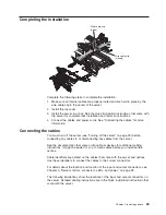
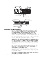
Page 35: ...server on page 29 before connecting any cables to or disconnecting any cables from the server See the documentation that comes with optional devices for additional cabling instructions It might be eas...

Page 36: ...with each option for information about installing device drivers The server comes with at least one microprocessor on the microprocessor board If more than one microprocessor is installed the server...

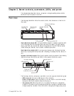
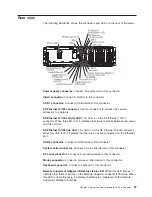
Page 37: ...ED On some server models each hot swap hard disk drive has an activity LED When this LED is flashing it indicates that the drive is in use Operator information panel This panel contains controls and L...

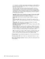
Page 38: ...m error has occurred An LED on the light path diagnostics panel is also lit to help isolate the error v Locator LED When this LED is lit it has been lit remotely by the system administrator to aid in...

Page 39: ...on the SP Ethernet 10 100 connector When this LED is lit it indicates that there is an active connection on the Ethernet port USB 2 connector Connect a USB device to this connector System serial conn...

Page 40: ...r is connected to an ac power source but is not turned on the operating system does not run and all core logic except for the service processor is shut down however the server can respond to requests...

Page 41: ...leave it connected to ac power the server can respond to requests from the service processor such as a remote request to turn on the server While the server remains connected to ac power one or more f...

Page 42: ...em and turn off the server if your operating system supports this feature v If the operating system stops functioning you can press and hold the power control button for more than 4 seconds to turn of...

Page 43: ...elp you install the operating system For information about the supported operating system versions see the label on the CD If the ServerGuide Setup and Installation CD did not come with the server you...

Page 44: ...tify the server You can also save one or more commands as a text file and run the file as a script v Serial over LAN Establish a Serial over LAN SOL connection to manage servers from a remote location...

Page 45: ...Select Start Options then set Planar Ethernet PXE DHCP to one of the following settings v Disabled v Planar Ethernet 2 If you set Planar Ethernet PXE DHCP to Planar Ethernet 2 you must also set Run PX...

Page 46: ...O configuration If you are using LILO complete the following steps 1 Modify the etc lilo conf file a Add the following text to the end of the first default linux line Monitor b Comment out the map boo...

Page 47: ...nstall boot boot b message boot message linear image boot vmlinuz 2 4 9 e 12smp label linux initrd boot initrd 2 4 9 e 12smp img read only root dev hda6 image boot vmlinuz 2 4 9 e 12 label linux up in...

Page 48: ...nux operating system starts a LILO boot prompt is displayed instead of the graphical user interface Press Tab at this prompt to install all of the boot options that are listed To load the operating sy...

Page 49: ...ed by anaconda Note that you do not have to rerun grub after making changes to this file NOTICE You have a boot partition This means that all kernel and initrd paths are relative to boot eg root hd0 0...

Page 50: ...d initrd 2 4 9 e 12 img You must restart the Linux operating system after completing these procedures for the changes to take effect and to enable SOL SUSE SLES 8 0 configuration Note This procedure i...

Page 51: ...olor white blue black light gray default 0 timeout 8 title linux kernel hd0 1 boot vmlinuz root dev hda2 acpi oldboot vga 791 1 initrd hd0 1 boot initrd title floppy root chainloader 1 title failsafe...

Page 52: ...en press Enter to display the current boot options for the server b In the Boot Entries section locate the boot entry ID for the section with an OS friendly name of Windows Server 2003 Standard Write...

Page 53: ...ti 0 disk 0 rdisk 0 partition 1 WINDOWS OS Load Options fastdetect redirect You must restart the Windows 2003 operating system after completing this procedure for the changes to take effect and to ena...

Page 54: ...m complete the following steps You must be logged in as a root user to perform these procedures 1 Go to http www ibm com pc support download the utility program and create the OSA BMC Management Utili...

Page 55: ...instructions on the screen Using the baseboard management controller firmware update utility program Use the baseboard management controller firmware update utility program to download a baseboard ma...

Page 56: ...SOL to remotely view and change the server BIOS settings At a command prompt type telnet localhost 623 to access the SOL network Type help at the smbridge prompt for more information Use the following...

Page 57: ...tem installed such as Microsoft Windows 2000 Datacenter Server see the software documentation that comes with the server for configuration information Using the PXE boot agent utility program The Preb...

Page 58: ...46 IBM xSeries 366 Type 8863 Installation Guide...

Page 59: ...in the drop down list follow the instructions on the Web page to download the latest version 2 Install the IBM Director program 3 Download and install any applicable updates or interim fixes for the s...

Page 60: ...48 IBM xSeries 366 Type 8863 Installation Guide...

Page 61: ...g charts These charts list problem symptoms and steps to correct the problems See Troubleshooting charts on page 53 for more information v Diagnostic programs and error messages The system diagnostic...

Page 62: ...he order shown restarting the server each time 163 Real time clock error 1 Run the Configuration Setup Utility program select Load Default Settings make sure the date and time are correct and save the...

Page 63: ...r has requested memory resources that are not available 1 Change the order of the adapters in the PCI slots Make sure that the boot device is positioned early in the scan order 2 Make sure that the se...

Page 64: ...drive is installed make sure that only one drive is set as the primary drive Start the CD from the primary drive The RAID program cannot view all installed drives or the operating system cannot be ins...

Page 65: ...iver is installed for the CD DVD drive General problems v Follow the suggested actions in the order in which they are listed in the Action column until the problem is solved v See the parts listing in...

Page 66: ...Trained service technician only that step must be performed only by a trained service technician Symptom Action A problem occurs only occasionally and is difficult to diagnose Make sure that v All cab...

Page 67: ...ervice Guide to determine which components are customer replaceable units CRU and which components are field replaceable units FRU v If an action step is preceded by Trained service technician only th...

Page 68: ...and Service Guide to determine which components are customer replaceable units CRU and which components are field replaceable units FRU v If an action step is preceded by Trained service technician o...

Page 69: ...f the problem remains call for service Wrong characters appear on the screen If the wrong language is displayed update the BIOS code with the correct language If the problem remains call for service O...

Page 70: ...e customer replaceable units CRU and which components are field replaceable units FRU v If an action step is preceded by Trained service technician only that step must be performed only by a trained s...

Page 71: ...oftware problems v Follow the suggested actions in the order in which they are listed in the Action column until the problem is solved v See the parts listing in the Problem Determination and Service...

Page 72: ...ice driver is installed v Your operating system supports USB devices If the problem remains call for service Video problems See Monitor problems on page 56 Light path diagnostics Use light path diagno...

Page 73: ...tton is pressed Diagnosing problems using light path diagnostics LEDs in three locations on the server are available to help you diagnose problems that might occur during installation Use them in the...

Page 74: ...r supply if only one power supply is installed 2 Use 220 V ac input power 3 Reseat the following components a Power supply b Trained service technician only Power backplane 4 Replace the components li...

Page 75: ...Trained service technician only Failing microprocessor b Microprocessor tray 4 Replace the following components one at a time in the order shown restarting the server each time a Trained service techn...

Page 76: ...em Note The PCI or MEM LED might also be lit 1 See the BMC log and the system error log 2 If the PCI LED is lit follow the instructions for that LED 3 If the MEM LED is lit follow the instructions for...

Page 77: ...ling power supply 3 Remove optional devices 4 Use 220 V ac instead of 110 V ac TEMP A system temperature or component has exceeded specifications Note A fan LED might also be lit 1 See the BMC log or...

Page 78: ...66 IBM xSeries 366 Type 8863 Installation Guide...

Page 79: ...any problems without outside assistance by following the troubleshooting procedures that IBM provides in the online help or in the publications that are provided with your system and software The info...

Page 80: ...ns and appliances For information about which products are supported by Support Line in your country or region see http www ibm com services sl products For more information about Support Line and oth...

Page 81: ...ANY KIND EITHER EXPRESS OR IMPLIED INCLUDING BUT NOT LIMITED TO THE IMPLIED WARRANTIES OF NON INFRINGEMENT MERCHANTABILITY OR FITNESS FOR A PARTICULAR PURPOSE Some states do not allow disclaimer of e...

Page 82: ...countries or both UNIX is a registered trademark of The Open Group in the United States and other countries Java and all Java based trademarks and logos are trademarks or registered trademarks of Sun...

Page 83: ...roduct recycling and disposal This unit contains materials such as circuit boards cables electromagnetic compatibility gaskets and connectors which may contain lead and copper beryllium alloys that re...

Page 84: ...s or by unauthorized changes or modifications to this equipment Unauthorized changes or modifications could void the user s authority to operate the equipment This device complies with Part 15 of the...

Page 85: ...uct has been tested and found to comply with the limits for Class A Information Technology Equipment according to CISPR 22 European Standard EN 55022 The limits for Class A equipment were derived for...

Page 86: ...d part number Used in these countries and regions 02K0546 China 13F9940 Australia Fiji Kiribati Nauru New Zealand Papua New Guinea 13F9979 Afghanistan Albania Algeria Andorra Angola Armenia Austria Az...

Page 87: ...hamas Barbados Belize Bermuda Bolivia Brazil Caicos Islands Canada Cayman Islands Costa Rica Colombia Cuba Dominican Republic Ecuador El Salvador Guam Guatemala Haiti Honduras Jamaica Japan Mexico Mic...

Page 88: ...76 IBM xSeries 366 Type 8863 Installation Guide...

Page 89: ...26 problems 53 E electrical input 4 electronic emission Class A notice 72 electrostatic discharge connector 26 environment 4 error messages POST 50 Ethernet connector 27 transmit receive activity LED...

Page 90: ...installing 41 OVERSPEC LED 62 P PCI BRD LED 65 PCI LED 64 pointing device problems 55 POST error messages 50 power control button 25 control button shield 25 cord connector 27 cords 74 LED 26 problems...

Page 91: ...s and notices 3 system error LED 26 T TEMP LED 65 temperature 4 trademarks 70 transmit receive activity LED Ethernet 28 troubleshooting chart 53 turning off the server 29 turning on the server 28 U Un...

Page 92: ...80 IBM xSeries 366 Type 8863 Installation Guide...

Page 93: ......

Page 94: ...Part Number 31R1515 Printed in USA 1P P N 31R1515...

Reviews: