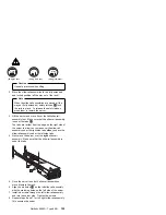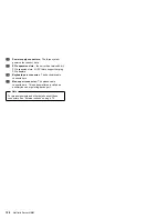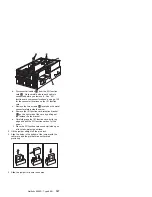
I/O board component locations
A simplified layout of the I/O board is shown in the
following illustration.
.1/
Midplane connector
.2/
I/O function card slot
.3/
Voltage regulator module (VRM) connectors
.4/
Advanced System Management PCI adapter slot
.5/
USB 1 and USB 2 port connectors
.6/
PCI switch card connector
.7/
Hot-plug, 64-bit, PCI slots 10–12 (bus A, 33 MHz)
.8/
Hot-plug, 64-bit, PCI slots 8–9 (bus B, 66 MHz)
.9/
Hot-plug, 64-bit, PCI slots 6–7 (bus C, 66 MHz)
.1ð/
Hot-plug, 64-bit, PCI slots 1–5 (bus D, 33 MHz)
.11/
Hot-plug external attention/fail LED for PCI slot
(green blink = attention, amber = defective PCI
adapter)
.12/
Hot-plug internal attention/fail LED for PCI slot
(green blink = attention, amber = defective PCI
adapter)
.13/
Hot-plug power LED for PCI slot (green solid,
on)
116
Netfinity Server HMM
Summary of Contents for 8500R - Netfinity - 8681
Page 2: ......
Page 8: ...vi Netfinity Server HMM...
Page 25: ...1 LVD low voltage differential Netfinity 8500R Type 8681 17...
Page 62: ...Caution Use safe practices when lifting 54 Netfinity Server HMM...
Page 242: ...I O Housing Assembly 1 2 3 4 5 6 7 234 Netfinity Server HMM...
Page 261: ...Related service information 253...
Page 262: ...254 Netfinity Server HMM...
Page 263: ...Related service information 255...
Page 264: ...256 Netfinity Server HMM...
Page 265: ...Related service information 257...
Page 278: ...270 Netfinity Server HMM...
Page 279: ...Related service information 271...
Page 280: ...272 Netfinity Server HMM...
Page 290: ...IBM Part Number 37L5123 Printed in U S A S37L 5123...


